
JIS G3461 Boiler and Heat Exchanger Steel Tubes
Engineered for Extremes: A Comprehensive Study of JIS G3461 Boiler and Heat Exchanger Steel Tubes
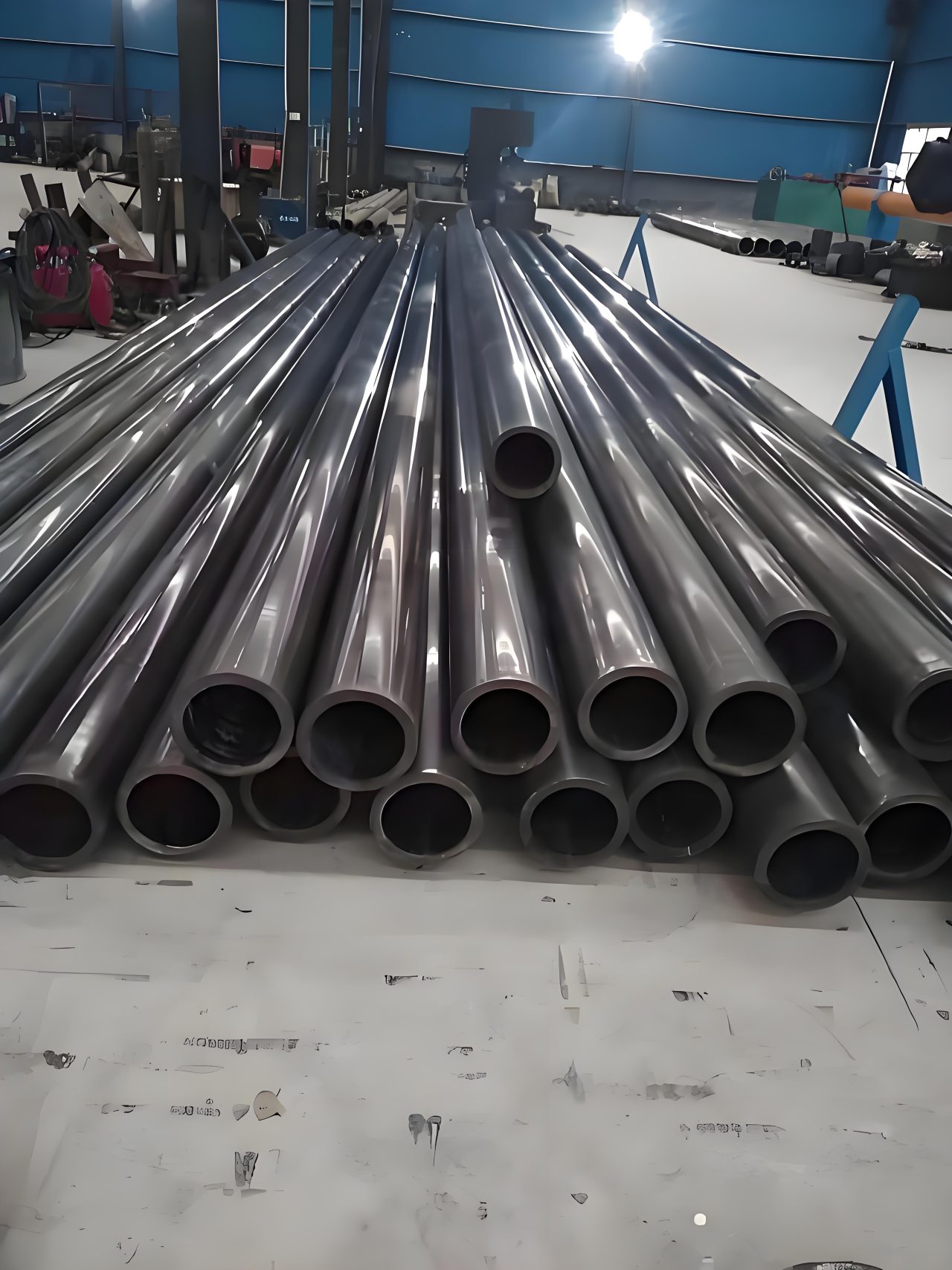
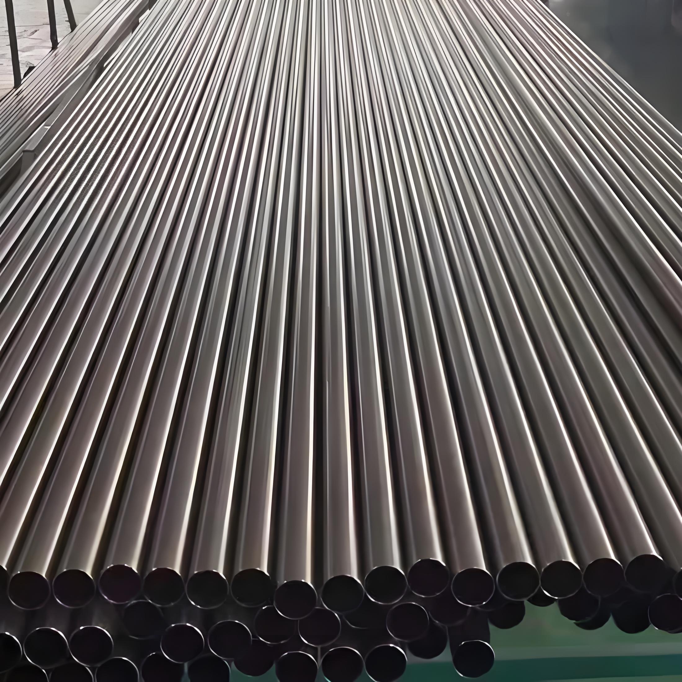
In the vast, interconnected world of industrial power generation and thermal processing, the boiler stands as the single most critical component, a high-pressure furnace where the raw power of heat is converted into usable energy. The integrity of this entire operation rests upon the unseen performance of thousands of feet of **boiler tubes**. These are not mere conduits for water or steam; they are sophisticated heat transfer devices that must simultaneously withstand immense internal pressures, aggressive external heat flux, severe thermal cycling, and the relentless, slow-motion threat of **creep deformation**. To ensure safety, reliability, and global interchangeability in this high-stakes environment, the **Japanese Industrial Standard (JIS) G3461** provides a highly specialized and rigorous set of specifications for **Carbon Steel Boiler and Heat Exchanger Tubes**. This standard is a technical covenant, dictating precise material science, manufacturing fidelity, and a mandatory gauntlet of testing.
The journey into JIS G3461 is a deep dive into the engineering compromises necessary for survival in extreme conditions. While other standards, such as JIS G3454, deal with pressure piping, G3461 operates on a different level of scrutiny. Its focus is explicitly on materials that perform the function of *heat exchange*, meaning the tube wall must manage a sharp thermal gradient. This critical function dictates the stringent requirements found within the standard’s grades—**STB 340, STB 410, and STB 510**—each a variation on a theme, optimized for distinct zones within the boiler, from the moderate heat of the economizer to the intense, pressure-laden environment of the evaporator and superheater sections. Understanding the requirements of G3461 means understanding the very backbone of modern thermal power.
I. The Standard’s Domain: Scope, Context, and Classification
The **JIS G3461** designation, with the **STB** (Steel Tube Boiler) identifier, specifies the necessary criteria for steel tubes used in transferring heat at elevated temperatures, typically up to a practical limit of around $450^\circ\text{C}$ to $500^\circ\text{C}$ for carbon steel, depending heavily on the internal pressure and the specific design code being applied (such as ASME). Above this threshold, metallurgical factors like **graphitization** (the precipitation of carbon that leads to brittle fracture) and accelerated creep necessitate the use of low-alloy chromium-molybdenum (Cr-Mo) steels, which are governed by the related standard, JIS G3462.
The three core grades within G3461 are defined by their minimum guaranteed ultimate tensile strength in megapascals ($\text{MPa}$):
- STB 340: The lower strength grade, favored for economizers and non-critical heat exchangers where temperatures and pressures are moderate, and high ductility is prioritized for ease of manipulation and coiling.
- STB 410: The workhorse of the standard. This mid-range strength provides an excellent balance of pressure capability, high-temperature performance, and reasonable weldability, making it ubiquitous in evaporator walls and general service boiler piping.
- STB 510: The highest strength carbon steel grade, often chosen when design pressures are extremely high, allowing for a thinner wall and maximized heat transfer efficiency, though requiring the highest level of control during welding and fabrication due to its increased carbon content.
The standard ensures not only strength but also dimensional uniformity and material consistency, which is paramount when hundreds or thousands of identical tubes must be seamlessly fitted, expanded, or welded into header drums and tube sheets. Without the rigid adherence to these specifications, the complex flow dynamics and thermal distribution within a boiler would be rendered unpredictable, potentially leading to catastrophic failure.
| Parameter | Specification | Grades Covered |
|---|---|---|
| Standard Name | Carbon Steel Boiler and Heat Exchanger Tubes | STB 340, STB 410, STB 510 |
| Designator | JIS G3461 (STB) | |
| Primary Function | Heat transfer and pressure containment up to $\approx 500^\circ\text{C}$ | |
| Typical Application | Economizers, Water-Wall Tubes, Evaporators, Low-Pressure Superheaters | STB 340 (Lower P/T), STB 410 (General P/T), STB 510 (High P/T) |
II. Method of Manufacture: The Integrity of the Tube Body
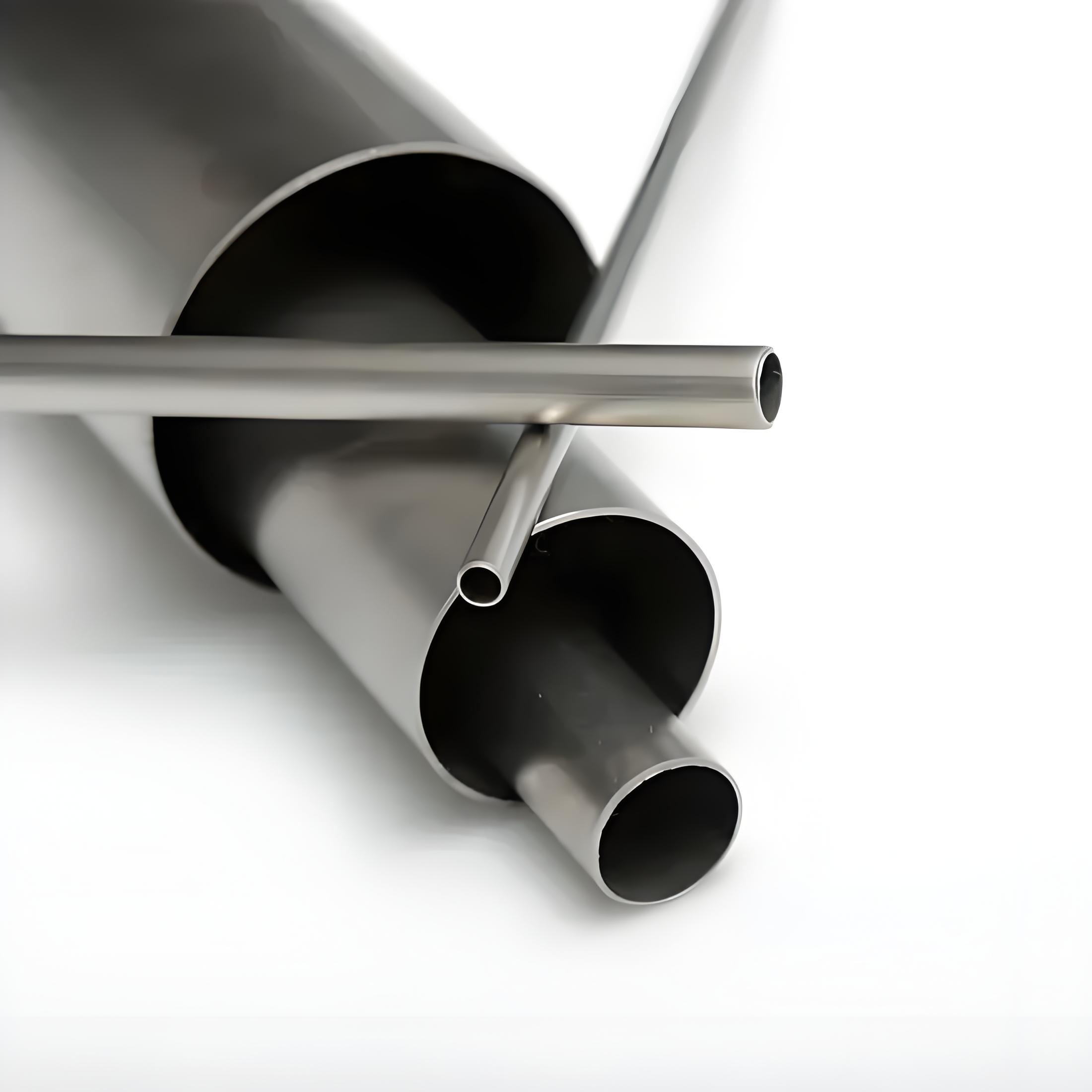
The manufacturing method is the foundation of the tube’s integrity and is categorized into two processes under JIS G3461: **Seamless (S)** and **Electric Resistance Welded (ERW) (E)**. The choice between these two is driven by the operating conditions, particularly the risk associated with the failure of a weld seam under stress.
Seamless Tubes (S): The Standard for High-Criticality
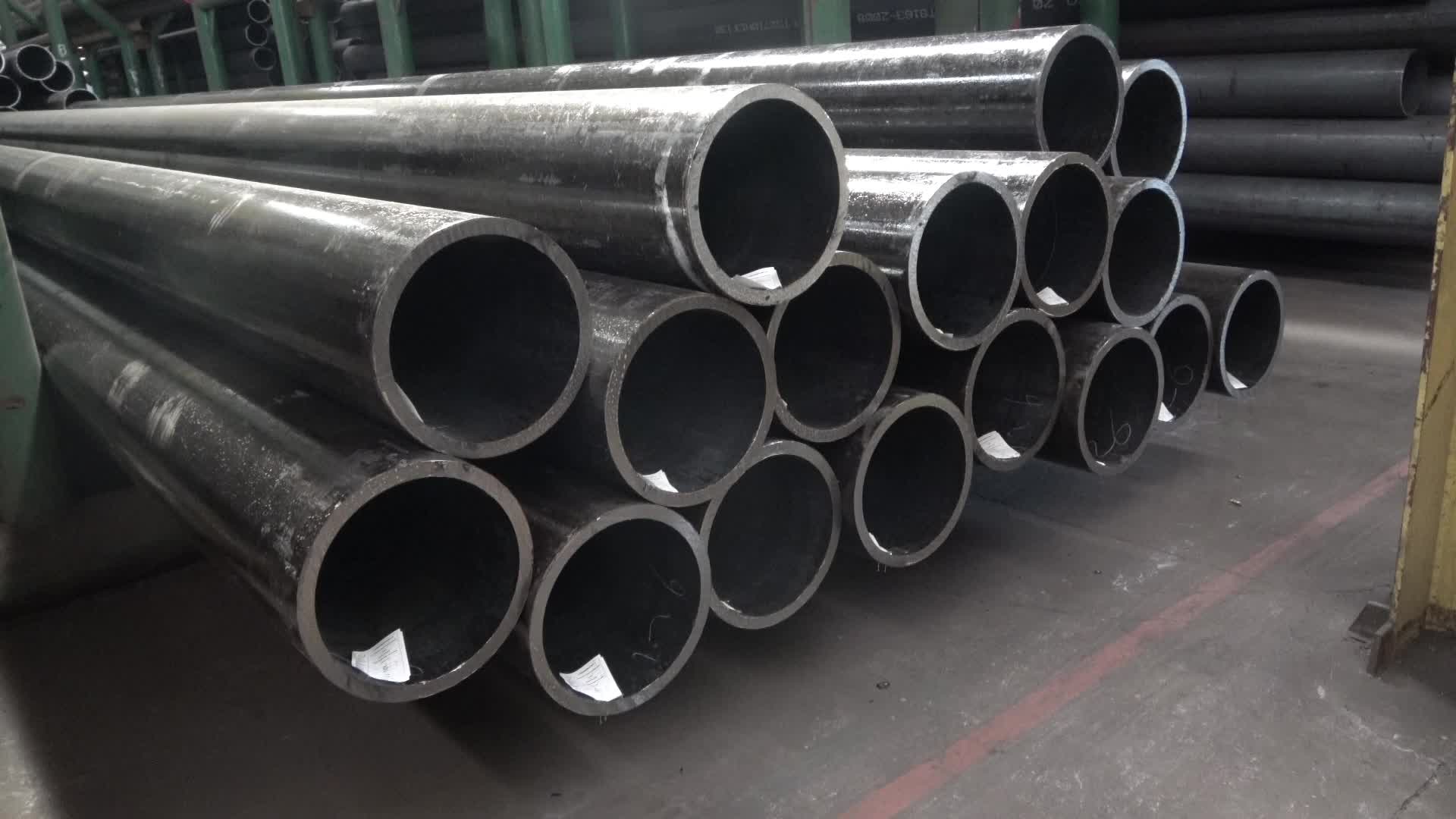
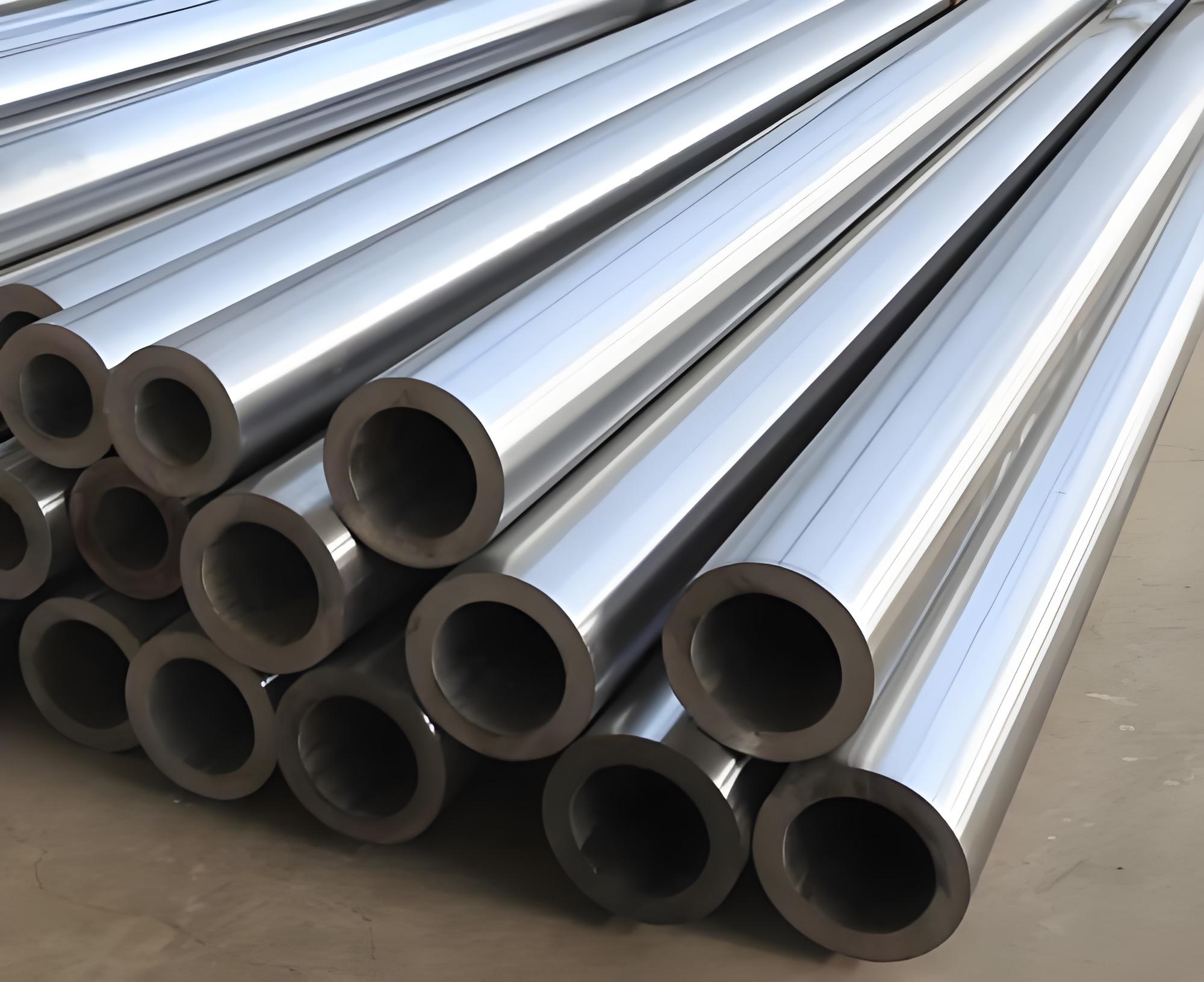
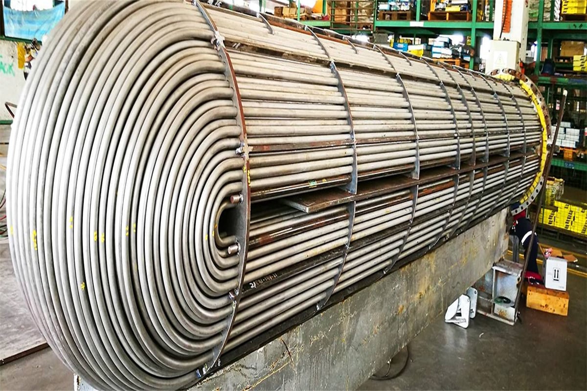
Seamless tubes are produced from a solid, cylindrical billet that is heated and pierced to create a hollow shell, which is then rolled and often cold-drawn to achieve the final size and wall thickness. The absence of any fusion or join ensures a continuous, uniform metallic structure free of the metallurgical discontinuities inherent in a weld. This is critical for tubes exposed to the highest internal pressures and **cyclic thermal loading**, such as in steam drums or furnace water walls, where a defect could quickly propagate into a failure. The seamless process allows the final product to have superior resistance to **creep rupture**, as the stress is distributed evenly across the entire circumference. Seamless tubes produced to G3461 specifications undergo mandatory final heat treatments—typically **normalization** for hot-finished tubes or **annealing** for cold-finished tubes—to relieve internal stresses and restore the optimal microstructure for long-term high-temperature service.
Electric Resistance Welded Tubes (E): Precision and Economy
ERW tubes are manufactured from continuous steel strip (skelp), which is cold-formed into a tube shape. The edges are joined by high-frequency electric current and pressure, fusing them without the addition of filler metal. Modern ERW processes are highly controlled and can achieve exceptional dimensional precision, particularly in wall thickness. This precision is sometimes favored in non-critical heat exchangers like economizers where the priority is thin, uniform walls for maximum heat transfer. However, because a weld seam is present, the standard demands rigorous verification. This includes mandatory post-weld **normalization** of the weld zone to ensure the grain structure in that area is equivalent to the base metal, followed by intensive non-destructive testing to guarantee the weld is free from flaws or lack of fusion.
| Type | Designator | Process | Mandatory Heat Treatment |
|---|---|---|---|
| Seamless | S | Hot piercing, rolling, (optional cold drawing) | Normalization (Hot-finished) or Annealing (Cold-finished) |
| ERW | E | Cold forming, High-frequency welding | Normalization/Stress Relief of the weld seam and adjacent HAZ |
*Note: Heat treatment is critical to achieve the specified mechanical properties, relieve residual stress, and ensure microstructural stability for high-temperature creep performance.
III. Chemical Composition: Balancing Strength and Integrity
The chemical recipe for JIS G3461 steel is not arbitrary; it is an optimized formula designed to maximize desirable properties while minimizing detrimental ones. The composition must ensure the necessary strength at elevated temperatures, prevent failure from high-temperature mechanisms, and maintain excellent **weldability**—an essential feature for tube-to-tube sheet connections.
The primary elements are controlled to create the differences between the grades. The carbon content ($\text{C}$) is the single most important factor determining the strength, increasing slightly from STB 340 to STB 510 to achieve the higher tensile properties. However, this comes with a trade-off: higher carbon content complicates field welding, increasing the risk of brittle microstructures in the heat-affected zone (HAZ) unless strict pre- and post-weld heat treatments are followed.
The essential roles of **Manganese ($\text{Mn}$) and Silicon ($\text{Si}$)** involve deoxidation during steelmaking, refining the grain structure, and boosting strength. Manganese is also crucial for counteracting the effects of sulfur, improving the steel’s hot ductility. Conversely, the concentration of impurities—**Phosphorus ($\text{P}$) and Sulfur ($\text{S}$)**—is strictly capped at a low maximum ($\le 0.035\%$). This constraint is non-negotiable for boiler tubes, as these elements readily segregate to grain boundaries, dramatically reducing toughness and accelerating high-temperature embrittlement, thereby undermining the tube’s resistance to creep and thermal stress. The low limits ensure material cleanliness and predictable performance over the tube’s multi-decade design life.
| Grade | $\text{C}$ (Max) | $\text{Si}$ (Max) | $\text{Mn}$ | $\text{P}$ (Max) | $\text{S}$ (Max) |
|---|---|---|---|---|---|
| STB 340 | $0.20$ | $0.35$ | $0.30 – 0.90$ | $0.035$ | $0.035$ |
| STB 410 | $0.25$ | $0.35$ | $0.30 – 1.00$ | $0.035$ | $0.035$ |
| STB 510 | $0.30$ | $0.35$ | $0.30 – 1.00$ | $0.035$ | $0.035$ |
*Note: The minimum manganese content is crucial for toughness; the stringent maximum limits on P and S are essential for high-temperature service integrity.
IV. Mechanical Properties: The Measure of Endurance
The mechanical properties define the material’s resistance to pressure and deformation. The specified minimums for **Tensile Strength ($\sigma_{ts}$)**, **Yield Point/Strength ($\sigma_{y}$)**, and **Elongation** are the core criteria that determine a tube’s selection for a specific location within the boiler system.
The **Yield Strength** is the most critical number for design engineers, as it sets the maximum permissible stress. By design code mandates, the operating pressure stress must be kept at a fraction of the yield strength to ensure the tube remains in the elastic range for its entire lifespan. For a given internal pressure, the superior yield strength of **STB 410** over STB 340, or **STB 510** over STB 410, allows the design engineer to specify a **thinner wall thickness**. This saves material, reduces weight, and significantly improves the tube’s most important function: the transmission of heat from the fire side to the water side. A thinner wall means less resistance to heat flow, increasing the boiler’s thermal efficiency.
**Elongation**, a measure of the material’s **ductility**, is equally vital. It provides the assurance that the tube will not fail in a brittle manner under impact or during the intense forming processes required during boiler fabrication, such as flaring or expanding the tube ends to create a leak-proof mechanical joint with the tube sheet. As expected, the higher strength grades (STB 410 and STB 510) exhibit slightly lower minimum ductility than the STB 340, reflecting the inherent trade-off between strength and flexibility in carbon steel metallurgy.
| Grade | Tensile Strength (Min.) $\text{N/mm}^2 (\text{MPa})$ | Yield Point/Strength (Min.) $\text{N/mm}^2 (\text{MPa})$ | Elongation (Min.) (Varies by Test Piece) |
|---|---|---|---|
| STB 340 | 340 | 175 | $25\%$ |
| STB 410 | 410 | 215 | $22\%$ |
| STB 510 | 510 | 285 | $18\%$ |
*Note: The elongation value is highly dependent on the thickness and the specific test specimen (No. 4, No. 5, No. 11, No. 12) used in accordance with the standard.
V. Dimensional Tolerances: The Non-Negotiable Geometry of Heat Transfer
The adherence to precise dimensional tolerances in JIS G3461 is not simply a matter of aesthetics or ease of assembly; it is intrinsically linked to **creep life** and **thermal efficiency**. The standard mandates extremely tight controls on both the outside diameter (OD) and the wall thickness (WT).
The Criticality of Wall Thickness Tolerance
For a boiler tube, the **Wall Thickness** tolerance is the most crucial geometric parameter. Because stress is inversely proportional to thickness, any section of the tube that is thinner than specified will experience higher localized stress, accelerating the slow process of creep deformation. If the negative tolerance is too large (i.e., the tube is too thin), the design life can be severely compromised, leading to premature failure and dangerous hot spots. Therefore, G3461 specifies tight limits, often restricting the negative tolerance to be much smaller than the positive tolerance—sometimes as little as $\pm 10\%$ of the nominal WT, or even a strictly positive tolerance (e.g., $+15\%$ to $-0\%$) for high-risk, high-pressure tubes, guaranteeing the minimum thickness is always present.
Outside Diameter and Straightness
The **Outside Diameter (OD)** tolerance is critical for fit-up. Tubes must be precisely sized to fit into the drilled holes of the header drums and tube sheets. A tolerance that is too loose prevents the formation of a secure, leak-tight **expanded joint**. The OD tolerance is often specified as a fixed absolute value for smaller diameters, ensuring high precision. **Straightness** and **ovality** (out-of-roundness) are also strictly controlled to ensure the tubes can be properly coiled, bent, and inserted into complex heat exchanger bundles using automated machinery without binding.
| Dimension/Process | Outside Diameter (OD) Tolerance | Wall Thickness (WT) Tolerance (Typical) |
|---|---|---|
| Seamless (Hot-finished) | $\pm 1\%$ of OD, or $\pm 0.5 \text{ mm}$ (Smaller Sizes) | $+15\%$ / $-12.5\%$ |
| Seamless (Cold-finished) / ERW | $\pm 0.3 \text{ mm}$ to $\pm 0.5 \text{ mm}$ (Tighter Control) | $\pm 10\%$ |
| Straightness | Maximum deviation | $1 \text{ mm}$ per $1000 \text{ mm}$ length |
*Note: The negative wall thickness tolerance is the single most scrutinised dimensional check under this standard to guarantee design life and pressure capacity.
VI. Testing and Inspection: The Non-Negotiable Safety Checklist
The extreme service conditions faced by JIS G3461 tubes dictate a comprehensive and mandatory inspection and testing protocol. These tests are the final, non-negotiable proof that the tube meets all specifications and is fit for service. The protocol is divided into mechanical tests (verifying material properties) and non-destructive tests (verifying structural integrity).
A. Mandatory Mechanical and Ductility Tests
The core of the mechanical verification process involves subjecting samples to severe deformation:
- Tensile Test: Confirms the material meets the minimum strength properties listed in Table 4.
- Flattening Test: A section of the tube is crushed between parallel plates. The material must withstand this severe compression without evidence of cracking or flaws, demonstrating high ductility, especially at the weld line of ERW tubes.
- Flaring Test: The end of the tube is expanded outward to a specified percentage of its original diameter using a conical tool. This test is vital for confirming the material’s ability to undergo the plastic deformation necessary to be securely expanded into the tube sheet holes, a critical step in boiler assembly.
- Reverse Flattening Test (ERW Only): This test specifically targets the weld seam. The sample is flattened with the weld placed at the point of maximum bending stress to prove that the weld zone is as strong and ductile as the base metal, eliminating the risk of weld failure.
B. Non-Destructive Examination (NDE) and Integrity Check
These tests are designed to catch flaws invisible to the eye that could lead to catastrophic failure:
- Hydrostatic Test: Every single length of finished tube must be pressure-tested to a specified minimum pressure. This physical test verifies the tube’s pressure-tightness and structural integrity throughout its entire length.
- Ultrasonic (UT) or Eddy Current (ET) Testing: NDE is mandated to search for internal flaws like laminations, inclusions, or micro-cracks that could compromise the tube’s structure. For ERW tubes, this testing is highly concentrated on the weld seam, ensuring the highest level of integrity in that critical join.
| Test Type | JIS G3461 Requirement | Primary Function |
|---|---|---|
| Chemical Analysis | Ladle and Product Analysis | Confirm C, Mn, P, S content for creep and weldability. |
| Hydrostatic Test | Every tube length | Verify pressure containment and leak-tightness. |
| Flaring Test | Sample testing | Confirm ductility for tube-to-tube sheet expansion. |
| Flattening Test | Sample testing | Verify ductility and structural soundness, especially at welds. |
| NDE (UT or ET) | Every tube length (Weld Zone for ERW) | Detect internal/surface flaws invisible to the eye. |
The **JIS G3461** standard for Boiler and Heat Exchanger Steel Tubes is a fundamental element of global thermal engineering. It is a highly specialized specification that governs the material intended to operate at the edge of its physical limits. From the calculated chemical composition designed to optimize creep resistance, to the precise dimensional tolerances required for maximum heat transfer efficiency, every single requirement within the standard is a direct response to the non-negotiable demands of safety and performance. The selection of **STB 340, STB 410, or STB 510** is not merely a choice of strength, but a choice of the specific life-cycle characteristics required by the boiler’s operating zone. Ultimately, adherence to this rigorous standard ensures that the complex machinery of power generation remains predictable, reliable, and safe for its multi-decade service life.
Boiler Pipe Application: 1 General boiler pipes are mainly used to manufacture water-cooled wall pipes, boiling water pipes, superheated steam pipes, superheated steam pipes for locomotive boilers, large and small smoke pipes and arch brick pipes. 2 high pressure boiler tubes are mainly used to manufacture superheater tubes, reheater tubes, air ducts, main steam tubes, etc. for high pressure and ultra high pressure boilers.
Boiler Steel Pipes are critical components in many industrial applications, providing reliable performance under extreme conditions. By adhering to strict quality standards and understanding the key properties and classifications of these tubes, industries can ensure the safe and efficient operation of their thermal systems.
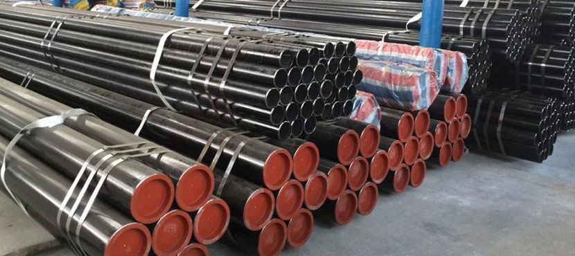
ASTM A210 Grade A1 Seamless Tube shall be made by the seamless or welding process with the addition of no filler metal in the welding operation. The offered ASTM A210 GR A1 CS Seamless Tubes is availed in diverse sizes and other related specifications, to meet requirements of our prominent clients.ASME SA 210 Gr.A1 Boiler Pipes that is designed according to set industry standards. As per the needs and requirements of our clients, we are involved in providing ASME SA 210 Gr. A1 Boiler Tubes. Buy ASTM A210 Grade A1 Boiler Tubes at reasonable cost from us.
ASTM B861 titanium alloy seamless pipes are a premium choice for boiler applications, offering unmatched corrosion resistance, high-temperature strength, and lightweight properties. Compliant with ASTM B861 and ASME SB861, these pipes in grades like 2, 7, and 12 meet the demands of power generation, chemical processing, and marine boiler systems. Despite higher costs, their durability and performance justify their use in critical applications. For technical data or quotes, contact suppliers like abtersteel.com
ASME SB338 Grade 7 titanium heat exchanger tubes, alloyed with palladium, offer unmatched corrosion resistance, thermal efficiency, and lightweight properties for demanding applications. Compliant with ASME SB338 and ASTM B338, these tubes excel in chemical processing, power generation, desalination, and marine heat exchangers. Their durability, enhanced by palladium, justifies their use despite higher costs. For technical data or quotes, contact suppliers like abtersteel.com
Coda: TP321 tubes, alloyed aegis of the blaze, orchestrate superheat—compositions cohesive, dimensions deft, strengths steadfast—eternal emissaries of energy's ember.