
PIPING SPOOL FABRICATION SYSTEM
Piping Spool Fabrication: A Comprehensive Analysis
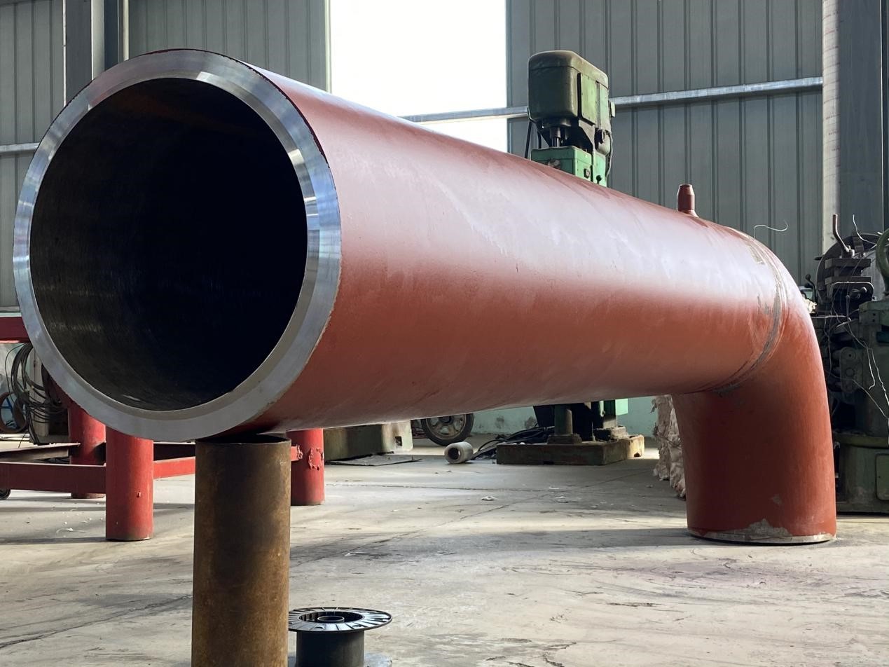
Definition: A pipe spool is a prefabricated section of a piping system, typically consisting of pipes, fittings (e.g., elbows, tees, reducers), flanges, valves, and other components, assembled in a controlled environment (e.g., a fabrication shop) before being transported to the construction site for installation. This modular approach streamlines project execution, enhances quality control, and reduces on-site labor, making it a cornerstone of modern industrial piping systems.
This analysis expands on the foundational concept by diving deeper into the fabrication process, advanced technologies, environmental considerations, cost optimization, and global industry trends. The structure includes:
- Introduction to Piping Spool Fabrication
- Key Parameters in Fabrication (with Tables)
- Scientific and Technical Analysis
- Advanced Materials and Their Applications
- Fabrication Processes and Technologies
- Quality Assurance and Industry Standards
- Environmental and Sustainability Considerations
- Cost Optimization Strategies
- Global Trends and Case Studies
- SEO Keywords for Enhanced Visibility
- Conclusion
1. Introduction to Piping Spool Fabrication
Piping spool fabrication is a specialized manufacturing process that involves assembling piping components into pre-engineered sections, or “spools,” that are ready for installation in industrial facilities. These facilities include oil refineries, chemical plants, power plants, water treatment facilities, and pharmaceutical manufacturing units. The prefabrication approach allows for precise fabrication under controlled conditions, minimizing errors, reducing on-site construction time, and improving safety by limiting hazardous fieldwork.
Key Benefits
- Quality Assurance: Controlled environments ensure consistent weld quality and dimensional accuracy.
- Efficiency: Parallel fabrication reduces project timelines by allowing simultaneous on-site and off-site work.
- Cost Savings: Minimizes field labor and rework, lowering overall project costs.
- Safety: Reduces on-site welding and heavy lifting, mitigating risks in hazardous environments.
- Scalability: Modular spools are ideal for large-scale projects with repetitive piping configurations.
Challenges
- Logistics: Transporting large or complex spools requires specialized equipment and planning.
- Material Selection: Components must be compatible with process fluids, temperatures, and pressures.
- Coordination: Precise design and measurement are critical to ensure spools align with on-site systems.
This analysis will explore these aspects in detail, providing a scientific foundation for understanding the fabrication process and its applications.
2. Key Parameters in Piping Spool Fabrication
The success of piping spool fabrication hinges on controlling critical parameters that influence the spool’s performance, durability, and compliance with industry standards. Below is a detailed table summarizing these parameters, followed by explanations of their significance.
Table 1: Key Parameters in Piping Spool Fabrication
| Parameter | Description | Typical Values/Standards | Impact on Fabrication |
|---|---|---|---|
| Pipe Diameter | Nominal diameter of the pipe (NPS or DN) | 1/2” to 48” (NPS), DN15 to DN1200 | Determines spool size, weight, and welding requirements. |
| Wall Thickness | Thickness of the pipe wall (Schedule or mm) | Sch 10, 40, 80, 160; 2–50 mm | Affects pressure rating, welding difficulty, and material costs. |
| Material Type | Material of the pipe and components | Carbon steel, stainless steel, alloy steel, etc. | Impacts corrosion resistance, strength, and weldability. |
| Weld Imperfection Criteria | Acceptable limits for weld imperfections (e.g., porosity, cracks) | ASME B31.3, API 1104, ISO 5817 | Ensures structural integrity and compliance with standards. |
| Bevel Angle | Angle of pipe end preparation for welding | 30°–37.5° (typically 37.5° for V-groove) | Affects weld penetration and strength. |
| Welding Process | Type of welding used (e.g., GTAW, SMAW, GMAW) | TIG, MIG, Stick, Submerged Arc | Determines weld quality, speed, and cost. |
| Fit-Up Tolerance | Alignment accuracy of components before welding | ±1–2 mm (depending on standard) | Ensures proper joint alignment and minimizes stresses. |
| Hydrostatic Test Pressure | Pressure applied during testing to ensure integrity | 1.5x design pressure (ASME B31.3) | Verifies spool integrity under operating conditions. |
| Surface Finish | Surface treatment (e.g., pickling, passivation, coating) | Ra 0.8–3.2 µm (for stainless steel) | Impacts corrosion resistance and fluid flow characteristics. |
| Dimensional Tolerance | Allowable deviation in spool dimensions | ±3 mm for length, ±1.5 mm for alignment | Ensures compatibility with field installation. |
| Heat Treatment | Post-weld heat treatment (PWHT) requirements | 600–700°C for carbon steel (if required) | Reduces residual stresses and improves weld durability. |
| Non-Destructive Testing (NDT) | Methods to detect defects (e.g., RT, UT, PT, MT) | Radiography, Ultrasonic, Dye Penetrant, Magnetic Particle | Ensures weld and material integrity without damaging the spool. |
| Spool Weight | Total weight of the fabricated spool | 10 kg to several tons | Affects transportation and lifting requirements. |
| Corrosion Allowance | Additional wall thickness to account for corrosion | 1–3 mm (depending on material and environment) | Extends service life in corrosive environments. |
| Thermal Expansion | Material expansion under operating temperatures | 12–16 µm/m·K (material-dependent) | Requires design considerations for expansion joints or supports. |
Explanation of Key Parameters
- Pipe Diameter and Wall Thickness: The diameter and wall thickness dictate the spool’s capacity to handle pressure and flow. Larger diameters accommodate higher flow rates but increase material and fabrication costs. Wall thickness, expressed as a schedule (e.g., Sch 40) or in millimeters, is selected based on pressure ratings and corrosion allowances.
- Scientific Consideration: The hoop stress (σ) in a pipe is calculated as:
σ = (P · D) / (2t)
where
Pis internal pressure,Dis outer diameter, andtis wall thickness. This ensures the spool withstands operational stresses. - Material Type: Materials like carbon steel, stainless steel, and alloy steel are chosen based on the process fluid, temperature, and environmental conditions. For example, stainless steel 316L is used in corrosive environments due to its molybdenum content, which enhances pitting resistance.
- Scientific Consideration: Material properties such as yield strength, thermal conductivity, and corrosion resistance are critical. For instance, carbon steel (ASTM A106) has a yield strength of ~240 MPa, suitable for moderate-pressure applications.
- Weld Imperfection Criteria: Weld imperfections (e.g., porosity, cracks) must comply with standards like ASME B31.3 or ISO 5817 to ensure structural integrity. Non-destructive testing (NDT) methods like radiography (RT) and ultrasonic testing (UT) detect subsurface defects.
- Scientific Consideration: Imperfections act as stress concentrators, reducing fatigue life. Acceptance criteria ensure welds meet performance requirements.
- Bevel Angle and Fit-Up Tolerance: A bevel angle of 30°–37.5° ensures proper weld penetration, while fit-up tolerances (±1–2 mm) minimize misalignment and residual stresses.
- Scientific Consideration: The bevel angle affects weld pool dynamics and the heat-affected zone (HAZ). Misalignment increases stress concentrations, risking premature failure.
- Welding Process: Processes like Gas Tungsten Arc Welding (GTAW/TIG) offer high precision, while Gas Metal Arc Welding (GMAW/MIG) is faster for high-volume production. Submerged Arc Welding (SAW) is used for large-diameter pipes.
- Scientific Consideration: Heat input, calculated as:
Q = (Voltage · Current · 60) / Welding Speed (mm/min)
affects the HAZ microstructure. Lower heat input reduces distortion and cracking risks.
- Hydrostatic Test Pressure: Hydrostatic testing at 1.5x design pressure (per ASME B31.3) verifies the spool’s integrity under operating conditions.
- Scientific Consideration: Testing ensures no leaks or deformations, validating weld and material quality.
- Surface Finish and Heat Treatment: Smooth surface finishes (e.g., Ra 0.8 µm for stainless steel) are critical in pharmaceutical applications to prevent bacterial growth. Post-weld heat treatment (PWHT) at 600–700°C reduces residual stresses in welds.
- Scientific Consideration: PWHT improves weld toughness by altering the HAZ microstructure, reducing risks like stress corrosion cracking.
3. Scientific and Technical Analysis
Piping spool fabrication integrates principles from materials science, mechanical engineering, fluid dynamics, and quality assurance. Below is a detailed analysis of these aspects.
3.1 Materials Science
Material selection is driven by operational requirements:
- Mechanical Properties: Yield and tensile strength determine the spool’s ability to withstand pressure and external loads. For example, alloy steel P91 (yield strength ~415 MPa) is used in high-temperature power plants.
- Corrosion Resistance: Stainless steel 316L has a corrosion rate of <0.1 mm/year in seawater, compared to >1 mm/year for carbon steel, making it ideal for marine applications.
- Thermal Properties: Materials with high thermal expansion (e.g., 16 µm/m·K for 316 SS) require expansion joints to prevent deformation in high-temperature systems.
Example Calculation
For a 12-inch (304.8 mm) carbon steel pipe (ASTM A106 Gr. B) with a 10 mm wall thickness and 50 bar (5 MPa) internal pressure:
With a yield strength of 240 MPa, the safety factor is:
This confirms the pipe’s suitability for the application.
3.2 Welding Science
Welding is critical to spool integrity:
- Heat Input: Excessive heat input causes grain growth in the HAZ, reducing toughness. GTAW with low heat input is preferred for high-alloy materials.
- Weld Imperfections: Porosity and cracks are minimized through proper shielding gas (e.g., argon for GTAW) and welder training.
- Residual Stresses: PWHT or controlled cooling mitigates stresses from thermal expansion and contraction.
3.3 Fluid Dynamics
The spool’s internal flow characteristics affect performance:
- Pressure Drop: Calculated using the Darcy-Weisbach equation:
ΔP = f · (L / D) · (ρ V² / 2)
where
fis the friction factor,Lis pipe length,Dis diameter,ρis fluid density, andVis velocity. - Flow Regime: Turbulent flow increases pressure drop and erosion. Smooth surfaces (e.g., electropolished stainless steel) reduce turbulence.
3.4 Structural Integrity
Spools must withstand internal pressure, external loads (e.g., seismic, wind), and thermal expansion. Finite Element Analysis (FEA) simulates stresses to ensure compliance with standards like ASME B31.3.
4. Advanced Materials and Their Applications
Beyond standard materials, advanced materials are increasingly used for specialized applications. Below is a table summarizing common and advanced materials.
Table 2: Materials for Piping Spool Fabrication
| Material | Standard | Applications | Advantages | Limitations |
|---|---|---|---|---|
| Carbon Steel (A106 Gr. B) | ASTM A106 | Oil and gas, water, steam | Cost-effective, high strength | Susceptible to corrosion |
| Stainless Steel (304/316) | ASTM A312 | Chemical, pharmaceutical, marine | Corrosion-resistant, durable | Higher cost, lower strength than carbon steel |
| Alloy Steel (P91, P22) | ASTM A335 | High-temperature power plants | High-temperature strength, creep resistance | Expensive, requires PWHT |
| Duplex Stainless Steel | ASTM A790 | Offshore oil and gas, corrosive environments | High strength, excellent corrosion resistance | Complex welding, high cost |
| Inconel 625 | ASTM B444 | Extreme corrosion, high-temperature systems | Exceptional corrosion resistance, high strength | Very expensive, challenging to weld |
| Titanium (Gr. 2) | ASTM B861 | Aerospace, chemical processing | Lightweight, corrosion-resistant | High cost, limited availability |
| HDPE | ASTM D3035 | Water, low-pressure chemical systems | Corrosion-resistant, flexible | Limited to low temperatures and pressures |
Scientific Considerations
- Corrosion: Duplex stainless steel and Inconel 625 offer superior resistance in aggressive environments like offshore platforms.
- Thermal Stability: Alloy steels like P91 resist creep at temperatures up to 600°C, ideal for power plants.
- Weldability: High-alloy materials like Inconel require specialized welding techniques (e.g., GTAW with precise heat control) to avoid cracking.
5. Fabrication Processes and Technologies
Piping spool fabrication involves multiple stages, each leveraging advanced technologies to enhance efficiency and quality.
5.1 Cutting and Beveling
- Process: Pipes are cut to precise lengths and beveled for welding using plasma cutting, laser cutting, or mechanical saws.
- Equipment: CNC pipe cutting machines, automated beveling systems.
- Advancements: Laser cutting offers ±0.1 mm precision, reducing material waste and ensuring accurate fit-up.
5.2 Welding
- Process: Common methods include GTAW, GMAW, and SAW. Orbital welding systems provide automated, high-precision welds for critical applications.
- Equipment: Orbital welders, robotic welding arms, TIG/MIG welders.
- Advancements: Robotic welding reduces human error and increases throughput, with real-time monitoring of weld parameters.
5.3 Assembly and Fit-Up
- Process: Components are aligned using jigs and clamps to ensure tight tolerances.
- Equipment: Automated alignment systems, laser-guided fit-up tools.
- Advancements: 3D scanning ensures precise alignment, reducing rework.
5.4 Inspection and Testing
- Process: NDT methods (e.g., RT, UT, PT) detect defects, while hydrostatic testing verifies integrity.
- Equipment: Digital X-ray systems, ultrasonic flaw detectors, pressure testing rigs.
- Advancements: Phased-array ultrasonic testing (PAUT) provides detailed defect mapping, improving inspection accuracy.
6. Quality Assurance and Industry Standards
Quality assurance ensures spools meet performance and safety requirements. Key standards include:
- ASME B31.3: Governs process piping design, fabrication, and testing.
- API 1104: Welding standards for pipelines.
- ISO 5817: Weld imperfection quality levels.
- ASTM/ASME Material Standards: Specify material properties (e.g., A106, A312).
Quality Control Measures
- Material Verification: Confirm material certificates and perform spectrometry for composition analysis.
- Weld Inspection: Use NDT to ensure welds meet acceptance criteria.
- Dimensional Checks: Verify spool dimensions using laser measurement tools.
- Pressure Testing: Conduct hydrostatic or pneumatic tests to confirm leak-tightness.
- Traceability: Maintain weld maps, test reports, and material records.
Scientific Consideration: Statistical process control (SPC) monitors defect rates, ensuring consistent quality. For example, control charts track weld imperfection frequency, maintaining compliance with ISO 5817.
7. Environmental and Sustainability Considerations
Piping spool fabrication has environmental implications, particularly in material use, energy consumption, and waste management:
- Material Efficiency: Optimize cutting patterns to minimize scrap. CNC nesting software reduces material waste by 10–15%.
- Energy Use: Automated welding and cutting systems consume significant energy. Energy-efficient equipment (e.g., inverter-based welders) reduces consumption by up to 20%.
- Coatings and Treatments: Environmentally friendly coatings (e.g., water-based paints) reduce volatile organic compound (VOC) emissions.
- Recycling: Scrap metal from cutting is recycled, with steel recycling rates exceeding 90% in many regions.
- Sustainability Trends: Use of high-density polyethylene (HDPE) for low-pressure systems reduces environmental impact due to its recyclability and corrosion resistance.
Scientific Consideration: Life cycle assessment (LCA) quantifies environmental impacts, guiding material and process selection to minimize carbon footprints.
8. Cost Optimization Strategies
Cost optimization is critical for competitive fabrication:
- Automation: Robotic welding and CNC cutting reduce labor costs by 15–30%.
- Lean Manufacturing: Eliminate waste through just-in-time material delivery and optimized workflows.
- Modular Design: Standardize spool designs to reduce engineering time and material costs.
- Digital Tools: Building Information Modeling (BIM) and 3D CAD prevent design errors, reducing rework costs by up to 20%.
- Supply Chain Management: Strategic sourcing and bulk purchasing lower material costs.
Scientific Consideration: Linear programming optimizes costs:
where Cm is material cost, Cl is labor cost, and Ct is transportation cost, subject to constraints like project deadlines and quality standards.
9. Global Trends and Case Studies
Global Trends
- Industry 4.0: Integration of IoT and AI in fabrication shops enables real-time monitoring of weld quality and production efficiency.
- Sustainability: Increased demand for eco-friendly materials like HDPE and low-emission coatings.
- Offshore Expansion: Growth in offshore oil and gas projects drives demand for corrosion-resistant spools (e.g., duplex stainless steel).
- Pharmaceutical Growth: Rising demand for sterile piping systems in biopharma facilities.
Case Study 1: LNG Plant Piping
A liquefied natural gas (LNG) plant required 1,000 spools for cryogenic service, using stainless steel 316L and Inconel 625. Challenges included:
- Low-Temperature Performance: Materials had to withstand -160°C.
- Corrosion: Exposure to seawater required high corrosion resistance.
- Tight Schedule: Six-month fabrication timeline.
Solution
- Used orbital GTAW for precise welds.
- Implemented PAUT for 100% weld inspection.
- Employed BIM for clash detection with on-site systems.
Outcome
Delivered on time with zero defects during cryogenic testing.
Case Study 2: Biopharmaceutical Facility
A biopharma plant needed 316L stainless steel spools for a sterile water system. Requirements included:
- Surface Finish: Ra < 0.5 µm to prevent bacterial growth.
- Cleanliness: No contamination during fabrication.
- Compliance: FDA and GMP standards.
Solution
- Used automated orbital welding with argon shielding.
- Performed electropolishing and passivation.
- Conducted 100% RT and hydrostatic testing.
Outcome
Spools met stringent regulatory requirements, ensuring safe operation.
10. SEO Keywords for Enhanced Visibility
To optimize the content for search engines, the following keywords target relevant search intent:
- Primary Keywords:
- Piping spool fabrication
- Pipe spool manufacturing
- Prefabricated piping systems
- Industrial piping assembly
- Pipe spool production
- Technical Keywords:
- Pipe welding standards
- NDT for piping systems
- Hydrostatic testing for spools
- ASME B31.3 piping fabrication
- Weld imperfection criteria
- Material Keywords:
- Stainless steel pipe spools
- Carbon steel piping fabrication
- Inconel pipe spools
- Duplex stainless steel piping
- HDPE pipe spool manufacturing
- Industry Keywords:
- Oil and gas piping systems
- Petrochemical pipe fabrication
- Pharmaceutical piping solutions
- Power plant spool fabrication
- LNG plant piping systems
- Process Keywords:
- CNC pipe cutting technology
- Orbital welding for piping
- Pipe beveling methods
- Automated spool fabrication
- Piping fit-up tolerances
- Long-Tail Keywords:
- How to fabricate piping spools for oil and gas
- Best practices for stainless steel spool fabrication
- Optimizing pipe spool production efficiency
- Piping spool fabrication for pharmaceutical plants
- Advanced welding techniques for pipe spools
- Sustainability Keywords:
- Eco-friendly piping fabrication
- Sustainable pipe spool manufacturing
- Low-emission piping coatings
- Recyclable piping materials
SEO Strategy
- On-Page: Incorporate keywords in headings, meta descriptions, alt text for tables, and throughout the content.
- Content Marketing: Publish blog posts or whitepapers on specific aspects (e.g., “Orbital Welding in Pipe Spool Fabrication”).
- Backlinks: Collaborate with industry publications to link to the content.
- Local SEO: Include region-specific terms (e.g., “pipe spool fabrication USA”) for targeted markets.
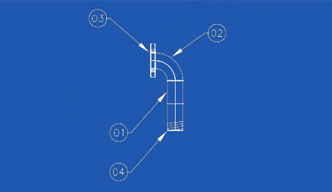 |
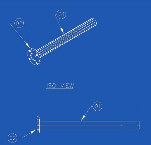
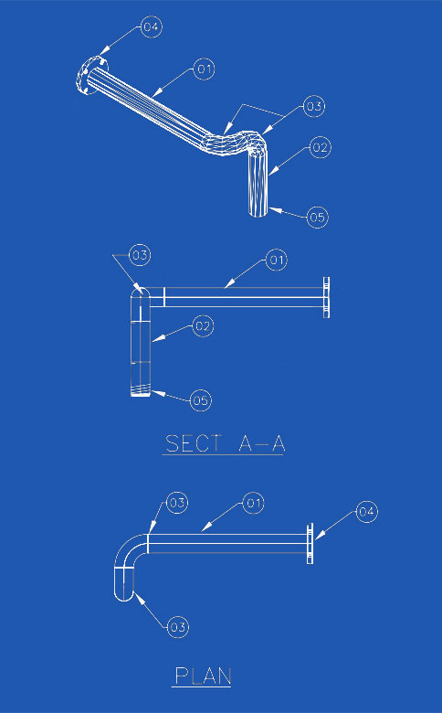
①Pipe, 3″ SCH 80 ②ELBOW 90°RAD 3″ SCH 80,BW ③Flange, RFSO, 3″ 150# ④6″ LG NIPPLE, SCH 80, BW |
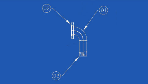 |
①ELBOW 90°RAD 3″ SCH 80,BW ②Flange, RFSO, 3″ 150# ③9″ LG NIPPLE, SCH 80, BW |
 |
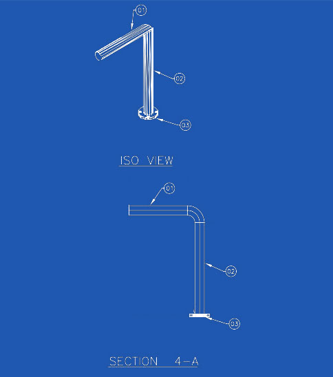
①ELBOW 90°RAD 3″ SCH 80,BW ②Flange, RFSO, 3″ 150# ③7 1/2″ LG NIPPLE, SCH 80, BW |
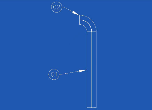 |
①Pipe, 3″ SCH 80 ②ELBOW 90°RAD 3″ SCH 80,BW |
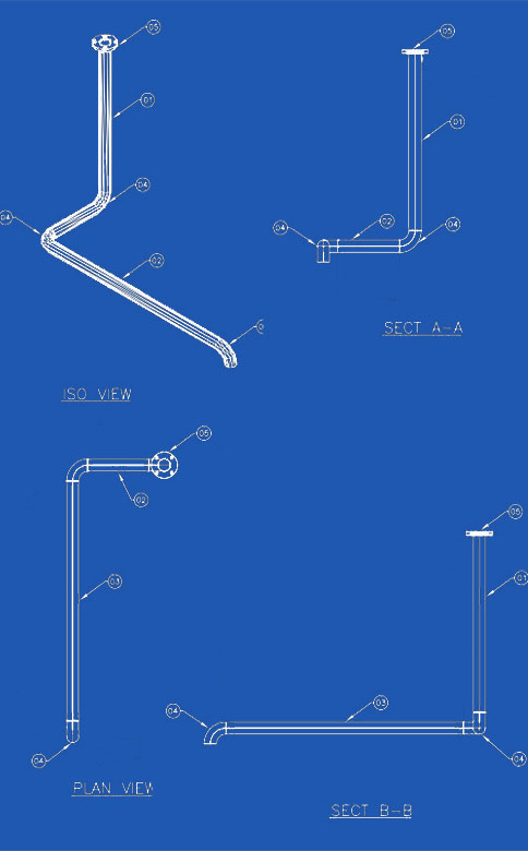 |
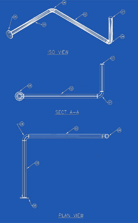
①Pipe, 3″ SCH 80 ②Pipe, 3″ SCH 80 ③Pipe, 3″ SCH 80 ④ELBOW 90°RAD 3″ SCH 80,BW ⑤Flange, RFSO, 3″ 150# |
 |
①Pipe, 3″ SCH 80 ②Pipe, 3″ SCH 80 ③Pipe, 3″ SCH 80 ④Pipe, 3″ SCH 80 ⑤ELBOW 90°RAD 3″ SCH 80,BW ⑥Flange, RFSO, 3″ 150# |
 |
①Pipe, 3″ SCH 80 ②Pipe, 3″ SCH 80 ③Flange, RFSO, 3″ 150# |
 |
①Pipe, 3″ SCH 80 ②Flange, RFSO, 3″ 150# |
 |
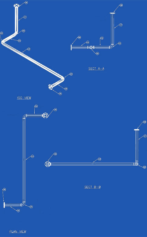
①Pipe, 3″ SCH 80 ②Pipe, 3″ SCH 80 ③Pipe, 3″ SCH 80 ④ELBOW 90°RAD 3″ SCH 80,BW ⑤Flange, RFSO, 3″ 150# |
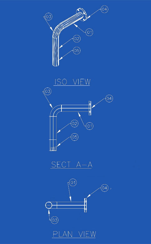 |
①Pipe, 3″ SCH 80 ②Pipe, 3″ SCH 80 ③ELBOW 90°RAD 3″ SCH 80,BW ④Flange, RFSO, 3″ 150# ⑤6″ LG NIPPLE, 3″ SCH 80, BW |
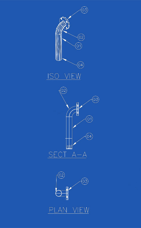 |
①Pipe, 3″ SCH 80 ②ELBOW 90°RAD 3″ SCH 80,BW ③Flange, RFSO, 3″ 150# ④6″ LG NIPPLE, 3″ SCH 80, BW |
 |
①Pipe, 3″ SCH 80 ②Pipe, 3″ SCH 80 ③ELBOW 90°RAD 3″ SCH 80,BW ④Flange, RFSO, 3″ 150# ⑤6″ LG NIPPLE, 3″ SCH 80, BW |
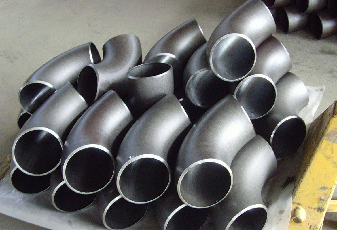
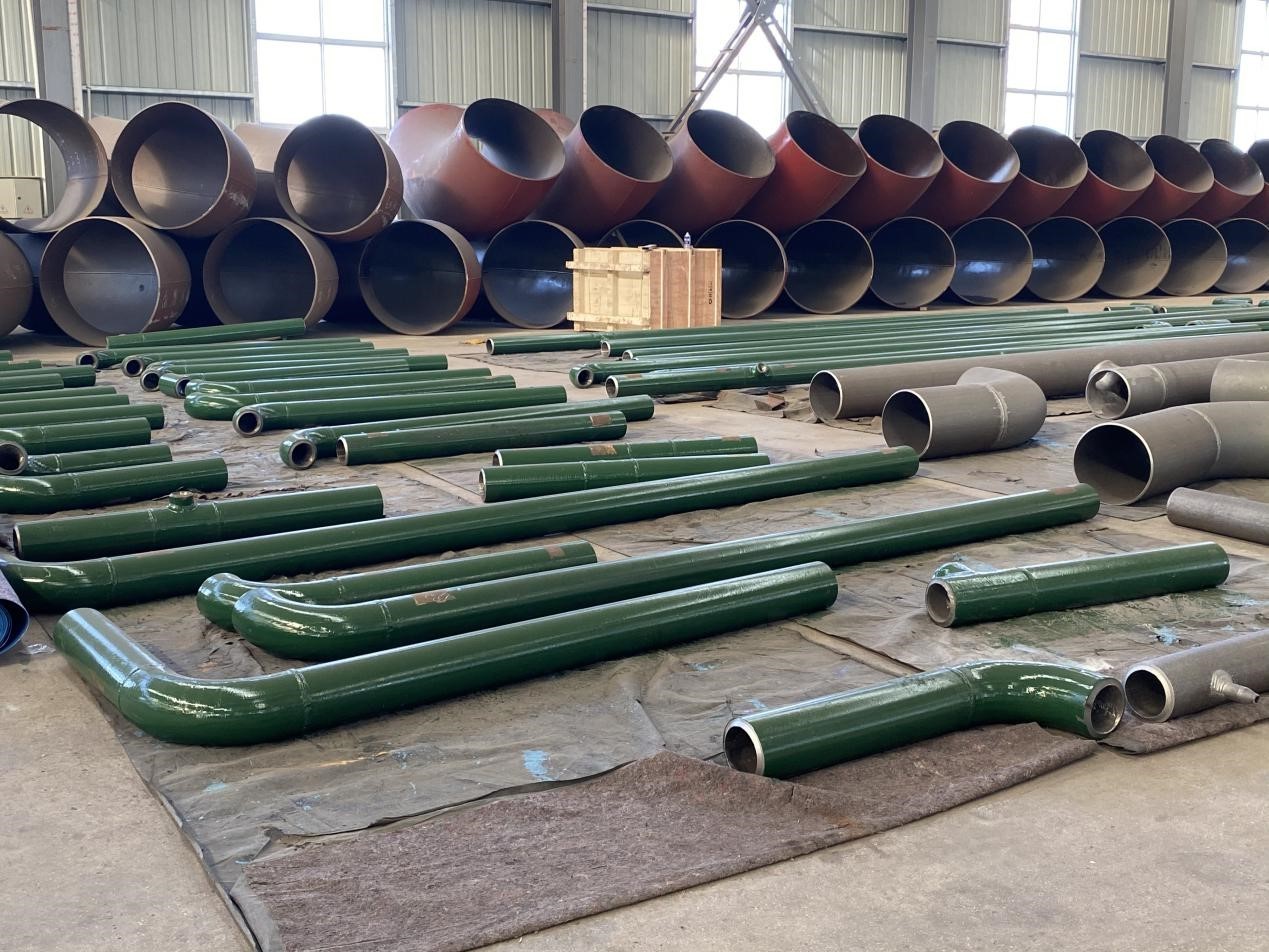
Pipe fittings are used in plumbing systems to connect straight sections of pipe or tubes, to accommodate different sizes or shapes, and for other purposes such as regulating (or measuring) fluid flow. These fittings are used in plumbing systems to control the transfer of water, gas or liquid waste within pipes or plumbing systems in domestic or commercial environments. Fittings (especially uncommon types) require money, time, materials and tools to install and are an important part of plumbing and plumbing systems. Common pipe fittings mainly include: flange, elbows, couplings, unions, spools, reducers, bushings, tees, diverter tees, crosses, caps, plugs, barbs and valves. Although valves are technically fittings, they are usually discussed separately.
Pipe fitting bodies are usually made of the same base material as the pipe or tubing they are connected to: copper, steel, PVC, CPVC or ABS. Any material permitted by plumbing, health or building codes (as applicable) may be used, but it must be compatible with the other materials in the system, the fluid being conveyed, and the temperature and pressure inside (and outside) the system. Brass or bronze fittings over copper Common in plumbing and plumbing systems. Fire resistance, shock resistance, mechanical strength, anti-theft and other factors also affect the choice of material for pipe fittings.
Material Stainless Steel ASME / ASTM SA / A403 SA / A 774 WP-S, WP-W, WP-WX, 304, 304L, 316, 316L, 304/304L, 316/316L, DIN 1.4301, DIN1.4306, DIN 1.4401, DIN 1.4404 Dimension ANSI B16.9, ANSI B16.28, MSS-SP-43 Type A, MSS-SP-43 Type B, JIS B2312, JIS B2313 Thickness Schedule 5S, 10S, 20S, S10, S20, S30, STD, 40S, S40, S60, XS, 80S, S80, S100, S120, S140, S160, XXS and etc.
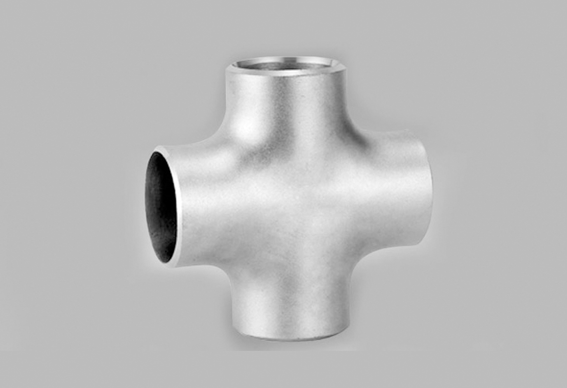
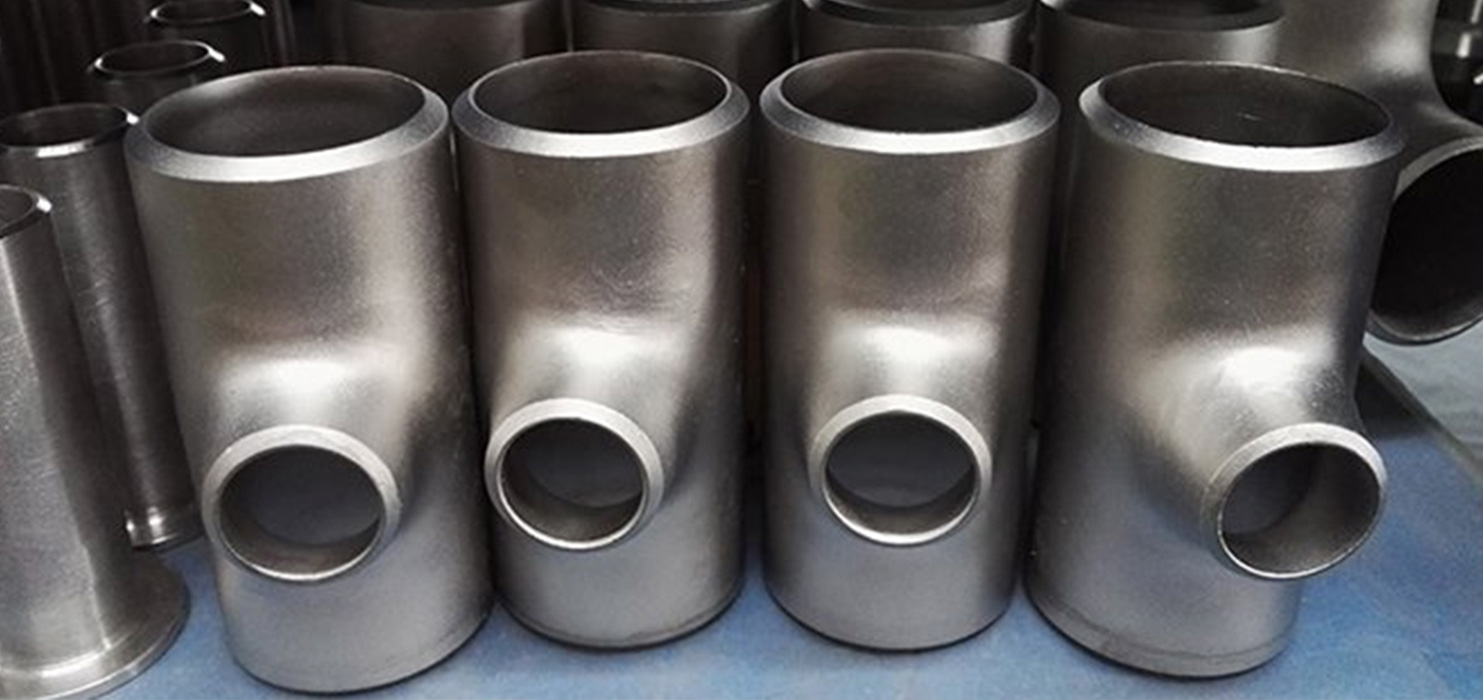
Cross fittings allow for the branching of pipes, enabling the distribution of water or other fluids to various fixtures or areas. They are commonly used in water supply systems, irrigation systems, and heating systems.
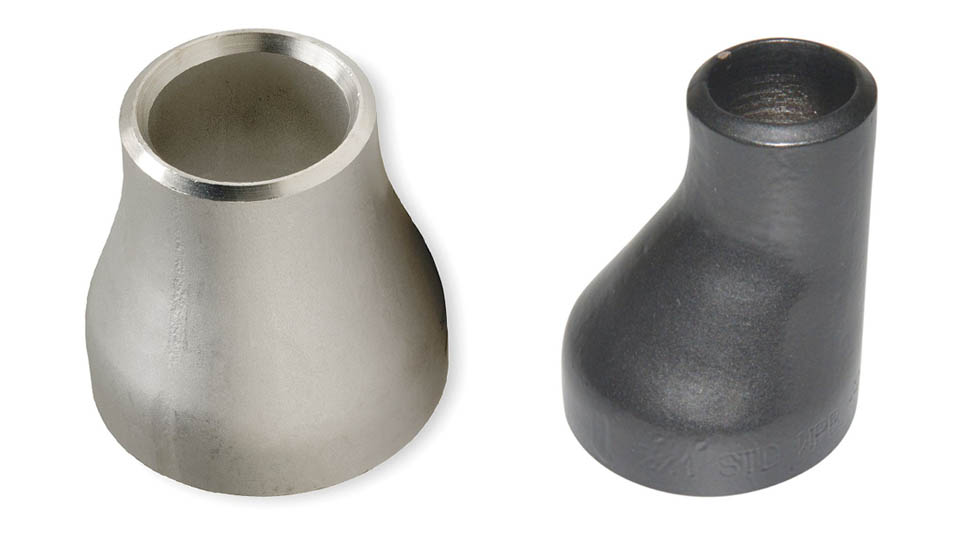
Concentric reducers are used where the pipework is vertically installed and at the discharge side of pumps. Eccentric reducers are more often used when the pipework lays on a pipe rack. Because of the flat side, aligning and securely mounting the pipes to the rack is easier.
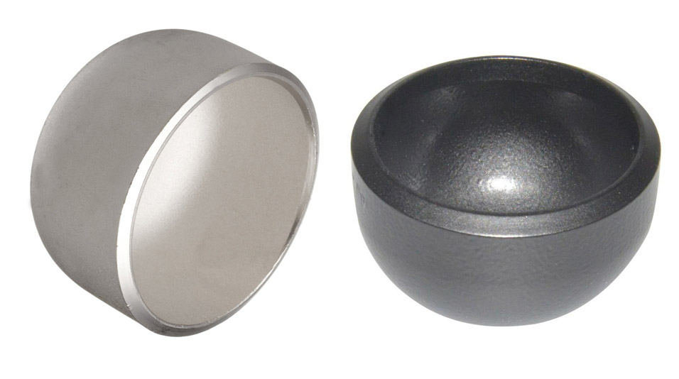
Butt Weld Cap We are manufacturer of butt weld cap and supplies all schedules in kinds of materials such as carbon steel, stainless steel, alloy steel. Zizi produces pipe caps in ASME, DIN, JIS and other required standards. Pipe cap is one of the common used pipe fittings for stoping fluid by covering at the pipe end. It is available in butt weld type, socket weld type and threaded type, and buttweld cap is more popular in view of the good performance, stable connection and large dimension selection range.