API 5L X52 / X60 Hot Induction Pipe Bends
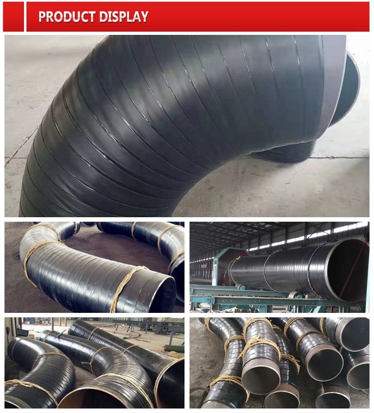
The Synthesis of Strength and Geometry: A Scientific Examination of API 5L X52/X60 Hot Induction Pipe Bends
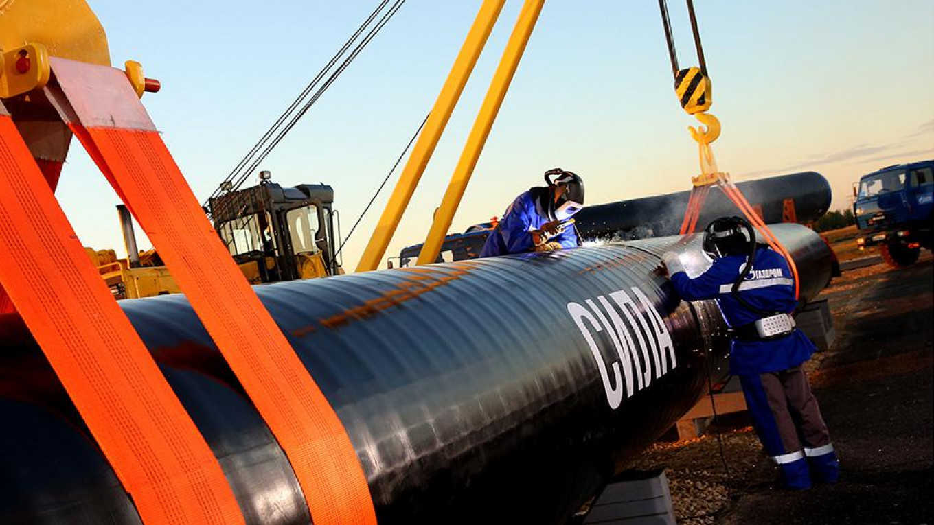
The modern transmission pipeline—the circulatory system of the global energy economy—is an intricate network defined by materials science and precision engineering. Within this network, the pipe bend is a critical, non-linear node where the constant force of high-pressure fluid flow meets the rigid necessity of directional change. Our product, the API 5L X52 and X60 Hot Induction Steel Pipe Bend, available in crucial and radii, is the embodiment of advanced thermal-mechanical processing applied to high-strength metallurgy. It is a highly engineered fitting designed to provide both structural integrity under extreme hoop stress and minimal hydraulic penalty, ensuring the long-term efficiency and safety of high-specification pipelines. Understanding this product requires a deep dive into the synergistic relationship between the chosen API 5L steel grade, the precise physics of hot induction bending, and the fundamental mechanical engineering principles governing pipeline flow.
The Metallurgical Engine: API 5L High-Strength Low-Alloy Steels
The foundation of performance for these bends lies in the sophisticated chemistry and processing of the API 5L line pipe specification. The grades and are categorized as High-Strength Low-Alloy () steels, which are specially developed to handle the intense stresses inherent in transmitting natural gas, crude oil, or refined products over vast distances. The number following the ‘X’ denotes the minimum specified Yield Strength in thousands of pounds per square inch (), a fundamental parameter that directly dictates the maximum allowable operating pressure and, consequently, the required wall thickness of the pipe.
The scientific achievement in these steels is the ability to achieve high yield strength— () and () respectively—without incurring the metallurgical penalties typically associated with high-strength materials, such as poor weldability or reduced fracture toughness. This balance is maintained through meticulous micro-alloying. Trace additions of elements like Niobium (), Vanadium (), and Titanium (), often totaling less than of the composition, are the key. During the steel’s processing, these micro-alloy elements form minute precipitates () and restrict the growth of crystal grains, resulting in an exceptionally fine-grained microstructure. This grain refinement is the primary scientific mechanism that simultaneously elevates the yield strength and preserves the low-temperature Charpy V-notch toughness that is essential for resisting brittle fracture, particularly in frigid environments or under transient loading.
Furthermore, the Carbon Equivalent () of these steels is strictly controlled to remain at low levels. A low is a chemical necessity because it ensures the material’s excellent weldability, minimizing the risk of forming brittle martensitic structures in the Heat Affected Zone () during field welding operations. The choice between X52 and X60 is, therefore, a precise engineering decision—a calculated leverage of the material’s strength to optimize wall thickness based on the design hoop stress, guided by pipeline design codes like . The strength of the metal allows the designer to achieve the desired pressure capacity with the minimal amount of steel, translating directly into reduced material cost, lower shipping weight, and increased ease of installation, all while maintaining a controlled Yield-to-Tensile strength ratio ( ratio) to guarantee sufficient ductility and strain capacity before failure.
The Physics of Formation: Hot Induction Bending and Microstructural Control
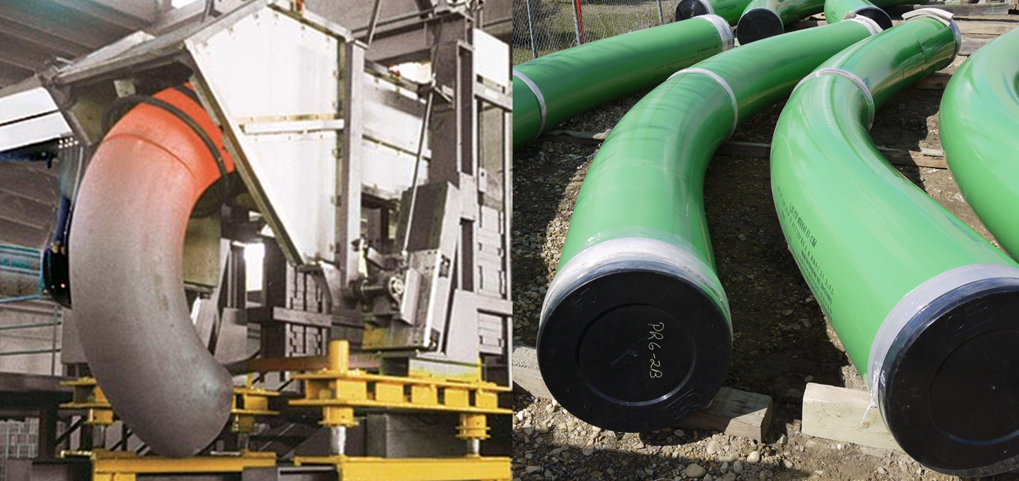
The creation of a precise pipe bend from high-strength steel cannot be achieved reliably through simple cold bending; the material would exhibit excessive springback, crack initiation, and uncontrolled geometric distortion. The necessary technology is Hot Induction Bending, a specialized thermo-mechanical process that relies on the precise application of electromagnetic energy and mechanical force.
The scientific core of this process is localized heating. The straight pipe is mounted in a bending machine, and a narrow induction coil encircles the bending zone. When high-frequency alternating current is passed through the coil, it generates a powerful alternating magnetic field. This field, according to Faraday’s law of induction, generates large eddy currents within the pipe wall, causing rapid and localized Joule heating. The bending zone is heated quickly and selectively to a precise temperature, typically between and —a range safely above the transformation temperature, making the material highly plastic and easy to form.
While the narrow band of the pipe is incandescent, a continuous mechanical force is applied, slowly pushing the pipe through the coil while a bending moment is exerted. This controlled, steady application of force causes the heated zone to deform plastically around a pivot point, forming the desired radius. This process is not just shaping; it is a rapid, localized heat treatment. The cooling rate immediately after the coil is crucial, often controlled by air or water sprays. This carefully managed thermal cycle is designed to prevent two simultaneous failure modes: first, grain coarsening at the high temperatures, which would lead to a catastrophic loss of toughness; and second, the formation of hard, brittle microstructures during rapid cooling. By controlling the cooling rate, the process aims to retain or even enhance the fine-grained structure established in the original parent material, ensuring that the finished bend maintains the specified or yield strength and the essential toughness.
The geometric challenge is managing the strain distribution. As the pipe bends, the material on the outer arc () is put into tension, leading to wall thickness thinning, while the inner arc () is compressed, causing wall thickness thickening. The thinning at the extrados is the most critical area, as it represents a local reduction in pressure containment capacity. The precision of the induction process, including the application of internal pressure or mandrels, is crucial for minimizing this thinning and ensuring the final wall thickness reduction remains within the strict limits (typically to ) mandated by pipeline codes and standards like ASME B31.8 and the specific induction bending standard, ASME B16.49. Any uncontrolled deviation here compromises the safety factor of the entire system.
Geometry, Hydraulics, and Mechanics: The Role of 5D, 8D, and 10D Ratios
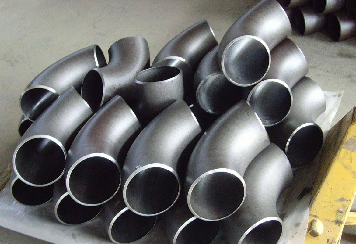
The specification of and bends—where the radius () is five, eight, or ten times the nominal diameter (), respectively—is a direct reflection of optimizing a balance between hydraulic efficiency and mechanical stress.
From a Hydraulic Engineering perspective, the size of the bend radius directly impacts flow characteristics. Tighter bends () induce greater secondary flow (swirling or helical flow patterns) and higher localized turbulence. This turbulence results in a greater pressure drop across the bend and necessitates higher pumping energy to maintain flow rate. Conversely, larger radii ( and ) facilitate smoother, more laminar-like flow redirection. The bend is often selected for the largest diameter, highest flow rate pipelines because it minimizes energy dissipation and reduces internal erosion/corrosion risks associated with flow separation. The choice, therefore, directly influences the operational cost and efficiency of the entire pipeline over its life.
From a Mechanical Engineering standpoint, the radius dictates the severity of the stress concentration. A tighter bend results in a higher Stress Intensification Factor () and lower flexibility factor compared to a bend. The concentration of hoop stress, axial stress, and the bending moments at the extrados and the flanks of the bend demands greater local mechanical integrity. The use of high-yield material in a tight radius is often necessary to ensure the combined operational and bending stresses do not exceed the material’s yield point, even after accounting for the wall thickness reduction inherent to the forming process. The ASME B31 codes provide the mathematical framework for calculating the exact stress limitations based on these geometric ratios and the material properties, ensuring a quantified factor of safety for the entire range of product offerings.
The ability to produce these three distinct radii using the hot induction process—each requiring precise adjustments to the coil heating pattern, forming speed, and cooling rates—demonstrates the technical mastery required. For example, forming a bend requires a far longer, gentler thermal application than a bend, demanding a more extended zone of controlled heating to achieve the wider radius without introducing geometric anomalies like wrinkling or excessive ovality.
Certification, Quality Control, and Final Product Integrity
The ultimate proof of performance for an induction bend lies in its compliance with rigorous quality control protocols and standards, chief among which is the final Hydrostatic Test. Every finished bend is subjected to internal pressure significantly higher than its maximum intended operating pressure (), stressing the metal beyond its nominal yield point. This is the definitive final step, providing proof that the material is free from critical defects and that the wall thickness integrity, even at the thinnest extrados, is sufficient to contain the design pressure.
Beyond the hydrostatic test, comprehensive Non-Destructive Evaluation () is mandatory. Ultrasonic Testing () is used to map the wall thickness profile across the entire bend, verifying that the thinning at the extrados remains within the code limits. Magnetic Particle Inspection () or Liquid Penetrant Inspection () is performed on the internal and external surfaces to search for microscopic surface-breaking flaws or cracks that could have initiated during the severe thermal and mechanical cycling of the induction process.
The final product, therefore, is an integrated component where the high-strength metallurgy of API 5L X52/X60 is perfectly matched to the controlled thermal physics of Hot Induction Bending. The resulting fittings, with their verified 5D, 8D, or 10D geometry, ensure that the pipeline can be constructed with confidence, maximizing flow capacity and minimizing maintenance requirements while adhering to the most stringent safety and engineering standards governing energy transportation infrastructure worldwide.
Product Specification Summary: API 5L X52/X60 Hot Induction Pipe Bends