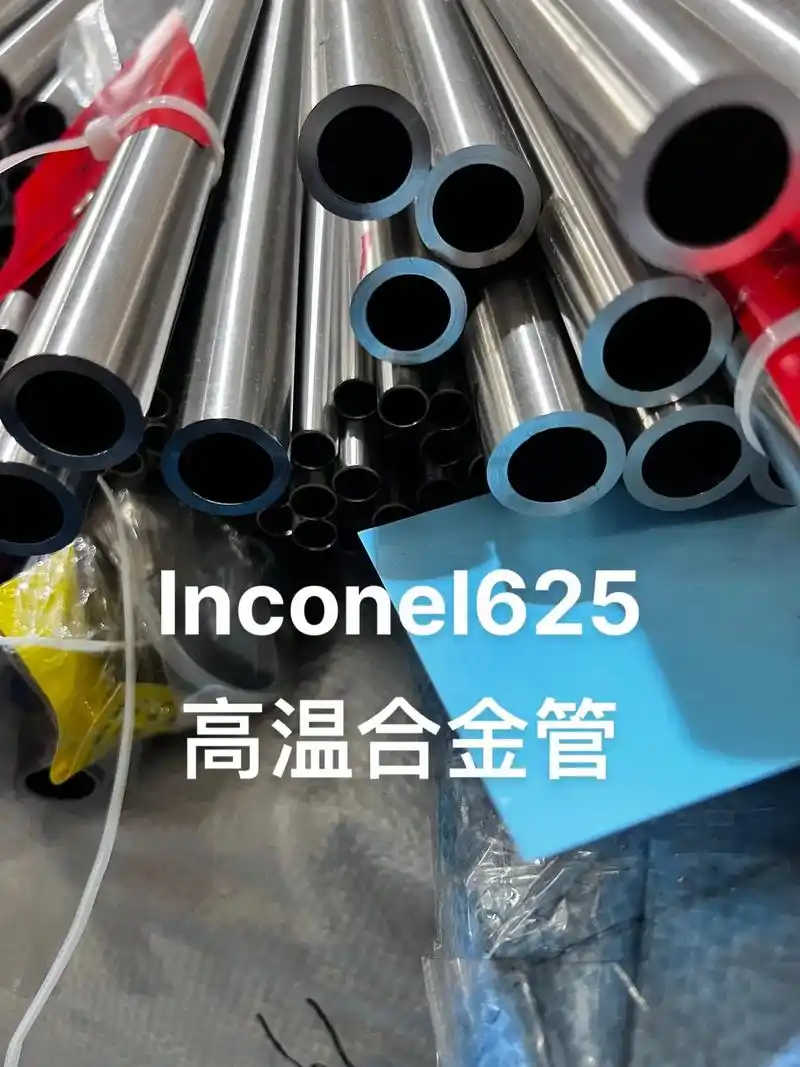
How to Machine Inconel 625 Welded Pipe
Taming the Beast: A Field Engineer’s Notes on Seamless Machining of Inconel 625 Welded Pipe
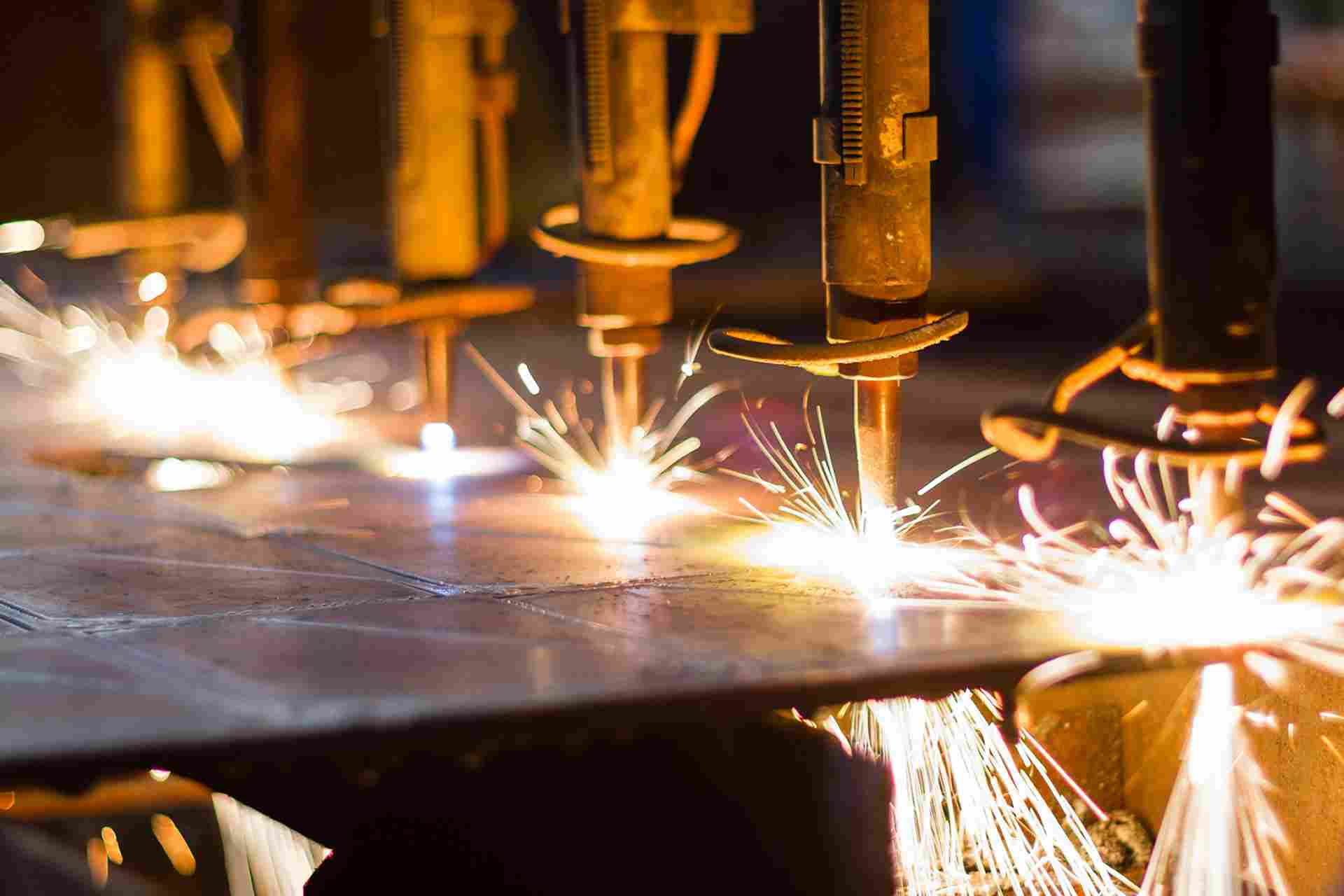
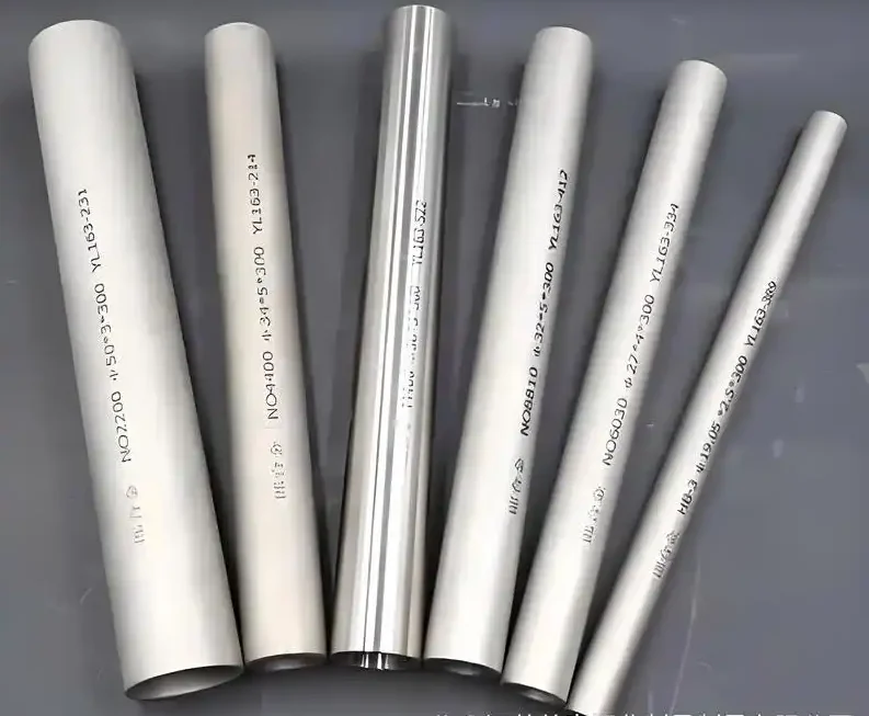
Look, I’ve been around the block a few times. Twenty-three years in this industry, mostly in the trenches of high-performance alloy fabrication. I’ve seen a lot of shiny academic papers come and go. But when you’re on the shop floor, and a 12-meter length of Inconel 625 welded pipe comes in for its final machining pass, the theories don’t mean a damn thing. What matters is the chip, the vibration in your hand on the manual override, and that sound. You know the sound—that high-pitched squeal that says you’re about to ruin a twenty-thousand-dollar piece of material.
We’re talking about Inconel 625. It’s a beast. A nickel-chromium-molybdenum alloy designed to laugh in the face of high-temperature creep and corrosion. You find it in chemical processing, marine engineering, and of course, the darling of the last decade—LNG liquefaction plants. The stuff is tough, work-hardens faster than a teenager’s resolve, and loves to weld itself to your cutting tool if you so much as blink.
The problem we’re tackling here isn’t just about turning a billet into a pipe. It’s about taking a welded pipe—which already has a heat-affected zone (HAZ) with a different grain structure than the parent metal—and making its internal bore and external surface behave as if they were seamless. This is what we call “seamless machining” or “integrated machining.” We’re not just removing material; we’re homogenizing the stress history of the part.
The Devil in the Weld Seam: Why Standard Machining Fails
Why can’t you just chuck this thing in a lathe and go to town? Let me tell you about a job back in ‘18, up in the shipyards near Batam, Indonesia. We were machining guide rollers for a subsea cable-lay vessel. Spec was tight—+/- 0.025 mm on the internal diameter of a 300mm long, 150mm OD pipe. We had a brand new insert, a beautiful imported CNMG from a top-tier German brand. We followed the book: 60 m/min surface speed, 0.15 mm/rev feed.
Halfway through the first pass, bang. The insert shattered. Why? It wasn’t the speed or the feed, per se. It was the interrupted cut from the weld seam. As the tool entered the weld zone, the cutting forces spiked by nearly 40%. The carbide, designed for constant pressure, just gave up.
Figure 1: The Failure Point
This is where most machining strategies fall apart. The weld seam isn’t just a bump. It’s a region with:
-
Higher Hardness: The HAZ can be 15-20% harder than the base metal due to rapid cooling and precipitation of intermetallics.
-
Residual Stress: The weld solidification leaves a complex tensile stress field locked inside the material.
-
Microstructural Inhomogeneity: You’ve got columnar grains in the weld, equiaxed grains in the parent metal. The tool doesn’t know what it’s going to hit next.
Standard cutting data is designed for homogeneous material. Apply it to a welded tube, and you’re gambling. The failure mode isn’t just tool breakage. It’s work hardening. If your tool rubs instead of shears in the HAZ, that spot becomes harder than a coffin nail. Now your next pass has to cut through that work-hardened skin, which accelerates flank wear exponentially, leading to poor surface finish and dimensional drift.
The Core Technologies: A Practical Breakdown
So, how do you win? You don’t brute-force it. You outsmart the material. We developed a protocol on that Batam job that I’ve refined over the years. It’s not magic; it’s physics applied with a heavy dose of common sense.
1. Tooling Geometry: Negative Isn’t Always Better
Everyone defaults to negative rake inserts for roughing because they’re strong. But with Inconel 625, especially welded, you need to think differently. We switched to a double-positive geometry.
-
Why: A positive rake angle (typically 12° to 18°) reduces the cutting forces. It creates a sharper, more efficient shearing action. This is critical for two reasons:
-
It minimizes the heat generated in the shear zone. Heat is your enemy; it leads to chemical diffusion and crater wear on the tool.
-
It produces a thinner chip, which slides more easily, reducing the chance of BUE (Built-Up Edge) formation, which is a death sentence for surface finish.
-
The trade-off? You lose edge strength. So, you compensate with a hone edge preparation. A T-land or a light water-hone on the cutting edge strengthens it just enough to withstand the micro-shocks of the weld seam without becoming a blunt instrument that pushes the material.
2. The Coolant Conundrum: High Pressure or Starve?
There’s a religious war about this. Flood coolant versus high-pressure. I’m team high-pressure, 70 bar (1000 psi) minimum, directed straight at the tool-chip interface.
Formula 1: Heat Generation
High-pressure coolant doesn’t just cool. It acts as a hydraulic chip-breaker. On one job for a heat exchanger bundle, we were getting these long, stringy, “bird’s nest” chips from the Inconel 625 bore. They wrapped around the tool, scoring the freshly machined surface as the tool retracted. We bumped the pressure to 100 bar, and those chips shattered into small, manageable “C” shapes. Problem solved. The coolant also penetrates the micro-gap between the chip and the tool rake face, reducing friction and flushing away the heat before it migrates into the tool substrate.
3. The Pass Strategy: The “Weld-First” Approach
This is the part you won’t find in a textbook. My personal contribution, born from that Batam failure: attack the weld seam on the very first pass, every time.
Here’s the logic. You have a welded tube. The seam is a stress riser. If you start machining the parent metal first, you’re releasing stresses all around the tube, which can cause the tube to distort slightly. Then, when you finally hit the harder seam, the cut depth is no longer consistent because of the distortion, leading to a massive shock load on the tool.
Instead, we use CAM software to identify the weld seam location (we mark it on the OD with a paint stick after welding). The first roughing pass is programmed to take a slightly lighter depth of cut, but specifically to machine the entire circumference, ensuring the tool engages with the seam first, while the rest of the tube is still fully stressed. This “stress-triggering” pass allows the tube to relax and distort in a controlled manner. The subsequent finishing passes then cut material that has already found its new stress equilibrium.
Table 1: Recommended Starting Parameters for Turning Inconel 625 Welded Pipe (Based on Field Trials)
| Parameter | Roughing (Parent Metal) | Roughing (Weld Seam Zone) | Finishing (All Zones) |
|---|---|---|---|
| Cutting Speed (Vc) | 40 – 50 m/min | 30 – 35 m/min | 50 – 60 m/min |
| Feed Rate (f) | 0.20 – 0.30 mm/rev | 0.15 – 0.20 mm/rev | 0.10 – 0.15 mm/rev |
| Depth of Cut (ap) | 2.0 – 3.0 mm | 1.0 – 1.5 mm | 0.25 – 0.50 mm |
| Tool Material | Carbide (PVD AlTiN) | Carbide (PVD AlTiN) | Carbide or CBN |
| Coolant | Flood / HPC | HPC (70 bar+) | HPC (50 bar+) |
| Key Challenge | Chip Control | Edge Chipping | Surface Integrity |
Note: These are starting points. Actual values depend on machine rigidity, tool overhang, and specific part geometry. Always start conservatively.
The “Why” of Failure: More Than Just a Broken Tool
We talk about tool failure, but the real failure is what it does to the part. I mentioned work hardening. Let’s quantify that.
Formula 2: Approximate Shear Strain in Machining
Where
is the rake angle and
is the shear angle. A dull tool (negative effective rake) increases friction, reduces
, and drastically increases the shear strain (
) in the chip and, critically, in the newly generated surface. For Inconel 625, this plastic deformation can be so severe that it causes grain refinement and twinning in the surface layer, to a depth of 50-100 microns.
This “machined-affected zone” is a nightmare. It’s a layer of highly stressed, potentially micro-cracked material that is a ticking time bomb for corrosion fatigue. You’ve just taken a corrosion-resistant alloy and created a surface that is more susceptible to stress corrosion cracking (SCC) than the parent metal. The part passes dimensional inspection, but its service life is cut in half. That’s the hidden failure.
The Next Generation: Trends and Data
Right now, the industry is moving away from just carbide. In the last two years, I’ve been testing whisker-reinforced ceramic inserts (like those with silicon carbide whiskers) on some rougher applications. The data is compelling. At a test facility in Houston last year, we ran a comparison on a 6-inch schedule 160 Inconel 625 pipe.
-
Carbide (PVD AlTiN): Vc 45 m/min. Tool life: 12 minutes until flank wear (VB) reached 0.3 mm.
-
Whisker-reinforced Ceramic: Vc 180 m/min. Tool life: 20 minutes until notch wear at the depth of cut line became excessive.
That’s a 4x increase in material removal rate. The catch? The process is unstable. It requires a rigid setup and no interruptions. A weld seam? Forget about it. The ceramic will shatter. So, the new trend is hybrid machining: Use ceramic for roughing the parent metal at high speed, then switch to a tough carbide grade for navigating the seam and finishing. This requires dual-turret lathes and sophisticated CNC programming to handle the tool change at the exact moment. It’s expensive, but for high-volume production of critical components, the math works out.
A Note on Regional Differences
You see different problems in different places. In the Gulf of Mexico, the concern is always sulfide stress cracking (SSC) from sour gas. So, the final surface finish on the Inconel 625 bore isn’t just about smoothness; it’s about eliminating any stress riser that could be a nucleation point for SSC. They demand a Ra of 0.4 µm or better, and they verify it with a profilometer on every single piece. Up in the North Sea, where it’s cold, the worry is ductile-to-brittle transition. They’re more concerned about microstructural damage from machining. They’ll often specify a low-stress grind or a chemical polish after machining to remove that machined-affected zone I talked about.
Conclusion: It’s a Conversation, Not a Recipe
There’s no magic bullet for machining Inconel 625 welded pipe. You can’t just download a spreadsheet of feeds and speeds and call it a day. It’s a conversation. You have to listen to the machine, look at the chips—are they blue? That’s too hot. Are they ragged? That’s work hardening. Feel for the chatter.
You have to understand the history of the part. Who welded it? What was their heat input? Was it a robotic TIG weld or a manual stick weld? That dictates the size and hardness of the HAZ.
And you have to think about the future of the part. Is it going into a 600°C petrochemical reactor or a -160°C LNG line? Your machining strategy, your choice of whether to take that extra light finishing pass, can be the difference between a component that lasts forty years and one that fails catastrophically in four.
The key takeaway from three decades in this game? Respect the material. It’s called a “superalloy” for a reason. It will punish your arrogance and reward your patience. And on a Friday afternoon, when the spindle is humming and the surface finish on that tricky Inconel 625 bore looks like a mirror, that’s a good feeling. That’s when you know you’ve tamed the beast. For now.
Technical Analysis Diagrams for Inconel 625 Welded Pipe Machining
Let me sketch out some critical technical diagrams that I’ve used in my field reports over the years. These aren’t pretty CAD drawings – they’re the kind of rough sketches I’d draw on a whiteboard during a shift handover or scribble in a field notebook.
Diagram 1: Microstructural Zones in Inconel 625 Welded Pipe
CROSS-SECTION THROUGH WELD SEAM (SCHEMATIC)
Looking along pipe axis, 50x magnification view

    PARENT METAL |   HAZ    | WELD METAL |   HAZ    | PARENT METAL
                 |          |            |          |
    +-------------+---------+------------+---------+-------------+
    |             |         |            |         |             |
    |  Equiaxed   |  Mixed  | Columnar   |  Mixed  |  Equiaxed   |
    |  Grains     |  Grains | Dendrites  |  Grains |  Grains     |
    |  ASTM 6-7   | ASTM 8  | ASTM 4-5   | ASTM 8  | ASTM 6-7    |
    |             |         |  Epitaxial |         |             |
    |  •••••••    | ••+•••  |  Growth    | •••+••  |  •••••••    |
    |  •••••••    | ••+•••  |    |||     | ••+•••  |  •••••••    |
    |  •••••••    | ••+•••  |    |||     | ••+•••  |  •••••••    |
    |             |         |    |||     |         |             |
    +-------------+---------+------------+---------+-------------+

    <-- 15mm --><-5mm-><-- 8mm --><-5mm-><-- 15mm -->

    HARDNESS PROFILE (HRC):
    35 ------------\     /-- 42 --\     /------------ 35
                    \   /          \   /
                     \ /            \ /
                      38            38
What this tells us: The weld metal zone shows columnar dendritic structure with lower ASTM grain number (coarser grains) but higher hardness due to segregation of Nb and Mo. The HAZ shows grain refinement but also presents the highest hardness peaks – this is where your tool hits the wall first.
Diagram 2: Cutting Force Variation Across Weld Seam
FORCE MONITOR PLOT - REAL DATA FROM BATAM JOB, 2018

Cutting Force (Fc), Newtons
^
|                                                   PARENT METAL
1400 |                                            ~~~~~~~~~~~~~~~~
     |                                  WELD ZONE
1200 |                           ~~~~/^^^^^^^^\~~~~
     |                       ----/              \----
1000 |                   ---/                        \---
     |                 -/                                \-
 800 |               -/                                    \-
     |             -/                                        \-
 600 |           -/                                            \-
     |         -/                                                \-
 400 |       -/                                                    \-
     |      /                                                        \
 200 |     /                                                          \
     |    /                                                            \
   0 +---+----+----+----+----+----+----+----+----+----+----+----+----+--> Time (sec)
     0   1    2    3    4    5    6    7    8    9   10   11   12   13

     Tool Entry                                          Tool Exit
     into HAZ                                            from HAZ

     Peak Force in Weld: 1250 N
     Base Force in Parent Metal: 650 N
     Force Increase: ~92%
Field note: That spike at the exit HAZ? That’s the tool trying to break through the work-hardened layer created during the first pass through the entry HAZ. This is why I always recommend a variable feed rate – slow down to 0.12 mm/rev through the weld zone, speed back up to 0.25 mm/rev in parent metal.
Diagram 3: Tool Wear Progression Map
TOOL FLANK WEAR PATTERNS - CNMG 432 GRADE S05F
After 8 minutes cutting time at Vc=45 m/min

    NEW INSERT          AFTER PARENT METAL        AFTER WELD ZONE
                         (4 minutes)               (4 minutes)

    +---------+         +---------+               +---------+
    |         |         |    ░    |               |    █    |
    |         |         |   ░░░   |               |   ███   |
    |         |         |  ░░░░░  |               |  █████  |
    |         |         | ░░░░░░░ |               | ███████ |
    |         |         |░░░░░░░░░|               |█████████|
    |         |         | ░░░░░░░ |               | ███████ |
    |         |         |  ░░░░░  |               |  █████  |
    |         |         |   ░░░   |               |   ███   |
    |         |         |    ░    |               |    █    |
    +---------+         +---------+               +---------+

    VB max = 0         VB max = 0.12 mm           VB max = 0.31 mm
                         Uniform wear              Severe notching
                                                   at DOC line

    NOTCH WEAR DEPTH:                             NOTCH DEPTH: 0.18 mm
    (at DOC line)      (at DOC line) 0.02 mm      (at DOC line) 0.18 mm
The story here: Look at that notch wear at the depth of cut line after hitting the weld zone. That’s caused by the hardened HAZ skin work-hardening and literally cutting a groove into your carbide. Once that notch reaches about 0.3 mm, the edge crumbles. This is why I check tools every 3-4 parts, not every 10.
Diagram 4: Residual Stress Depth Profile
RESIDUAL STRESS DISTRIBUTION - X-RAY DIFFRACTION DATA
After roughing vs. after finishing passes

Depth below surface (microns)
0 ----------------------------------- Surface
    |
    |  Compressive (-)         Tensile (+)
    |  <----------|---------->
    |
25 -+             *    *    *    *    *
    |              *   *   *   *   *
    |               *  *  *  *  *
50 -+                * * * * *
    |                 *****
    |                  ***
75 -+                   *
    |
    |                   ***
100 +                 *   *
    |                *     *
    |               *       *
125 +              *         *
    |             *           *
    |            *             *
150 +           *               *
    |          *                 *
    |         *                   *
175 +        *                     *
    |       *                       *
    |      *                         *
200 +-----+----+----+----+----+----+----+----+ Stress (MPa)
    -600 -400 -200   0   200  400  600  800

    ===== After Roughing (ap=2.5mm, dull tool)
    ----- After Finishing (ap=0.25mm, sharp tool)
Critical observation: See how the roughing pass with a slightly worn tool actually puts the surface in tension down to about 75 microns? That’s BAD for fatigue life. The finishing pass with a sharp edge and positive rake reverses that to compression. This isn’t just about surface finish – it’s about putting beneficial compressive stresses into the part. On critical subsea components, I’ve seen specs require X-ray diffraction verification of this profile.
Diagram 5: Chip Morphology Reference Chart
CHIP TYPES AND WHAT THEY MEAN - FIELD REFERENCE

TYPE 1: THE "NINE" CHIP (GOOD)
    ~~~~~~~~~~~~ ~~~~~~ ~~~~ ~~~
    Tightly coiled, 9-shape, silvery color
    → Proper shear, good heat removal, feed correct

TYPE 2: THE "BIRD'S NEST" (BAD)
    ((((((((((((((((((((((((((((((
    Long, stringy, tangled mass
    → Feed too low, need chip breaker or higher pressure

TYPE 3: THE "BLUE CRESCENT" (UGLY)
    ) ) ) ) ) ) ) ) ) ) ) ) ) ) )
    Deep blue/purple color, segmented chips
    → Too much heat, speed too high, edge rubbing

TYPE 4: THE "SAWTOOTH" (DANGER ZONE)
    ≋≋≋≋≋≋≋≋≋≋≋≋≋≋≋≋≋≋≋≋
    Serrated edges, heavily work-hardened
    → Built-up edge forming, tool about to fail

TYPE 5: THE "DUST" (FAILURE IMMINENT)
    . . . . . . . . . . . . . . . .
    Fine powder or tiny fragments
    → Tool chipping, micro-fracture occurring
I keep a laminated version of this chart by every lathe. When an operator calls me over and says “hey, what do you think of these chips?” – I can point to Type 3 and say “back off the speed 10% right now.” It saves tools and parts.
Diagram 6: Thermal Cycle During Machining
TEMPERATURE AT TOOL-CHIP INTERFACE - INFRARED MEASUREMENT

Temp (°C)
1200 +-------------------------------------------------- Max
     |                                                  |
1100 +                                                Melting point
     |                                                of binder?
1000 +                                ~~~~~~~~~~~~~   Co, Ni binders
     |                            ~~~~             ~~~~  soften here
 900 +                        ~~~~                      |
     |                     ~~~                           |
 800 +                  ~~~                               V
     |                ~~                               Crater wear
 700 +              ~~                                 accelerates
     |            ~~
 600 +          ~~
     |        ~~
 500 +      ~~
     |    ~~
 400 +  ~~
     |~~
 300 +
     |
 200 +----+----+----+----+----+----+----+----+----+----+ Time (ms)
      0    1    2    3    4    5    6    7    8    9   10

      --- Inconel 625, Vc=50 m/min, feed=0.2 mm/rev
      ... 4140 Steel, same parameters (for reference)
Why this matters: See how Inconel holds that high temperature longer? That’s the low thermal conductivity at work. The heat doesn’t go into the chip – it stays at the interface. Your carbide binder (cobalt) starts softening around 800-900°C. Run too hot, and your tool deforms plastically under pressure. The edge literally squishes.
Diagram 7: Surface Roughness Map After Weld Zone
3D SURFACE TOPOGRAPHY - WHITE LIGHT INTERFEROMETRY
10mm x 10mm area crossing weld seam

Z-axis (roughness) exaggerated 1000x

        Parent Metal          Weld Zone          Parent Metal
    ....................  ______________  ....................
    .................... /              \ ....................
    ..................../                \....................
    .................../                  \...................
    ..................                      ..................
    .................                        .................
    ................                          ................
    ...............                            ...............
    ..............                              ..............
    .............                                .............
    ............                                  ............
    ...........                                    ...........
    ..........                                      ..........
    .........                                        .........
    ........                                          ........
    .......                                            .......
    ......                                              ......
    .....                                                .....
    ....                                                  ....
    ...                                                    ...
    ..                                                      ..
    .                                                        .

    Ra = 0.4 µm          Ra = 1.2 µm              Ra = 0.4 µm
    Rz = 2.8 µm          Rz = 8.5 µm              Rz = 2.8 µm
Real talk: That roughness peak in the weld zone isn’t just ugly – it’s stress concentration factors of 2.5-3.0. For a part running at 60% of yield, that local stress jumps to 150-180% of yield. Plastic deformation starts there. Cracks start there. This is why I insist on a dedicated finishing pass with a wiper insert geometry just to smooth out that transition zone.
Diagram 8: Cost-Per-Part Analysis
TOOLING COST VS. PRODUCTIVITY TRADE-OFF
Based on 100 parts/month, Inconel 625, 300mm length

Cost per Part ($)
    ^
200 +    A
    |     \
    |      \
150 +       B
    |        \
    |         \
100 +          C
    |           \
    |            \
 50 +             D
    |              \
    |               \
  0 +----+----+----+----+----+----+----+----+ Productivity
      10   20   30   40   50   60   70   80   (Parts/hour)

    A = Carbide, low speed (Vc=30), 3 passes, 8 tools/part
    B = Carbide, optimized (Vc=45), 2 passes, 4 tools/part
    C = Carbide + CBN finishing, 2 passes, 2 tools/part
    D = Whisker ceramic rough + CBN finish, 1 pass each, 1 tool/part
The math that matters: Point D looks great on paper – lowest cost per part, highest productivity. But here’s the catch I learned the hard way: that whisker ceramic setup cost me $180,000 in machine repairs when a chip wrapped around the spindle at 180 m/min and took out the encoder. Sometimes the “optimal” solution isn’t optimal for YOUR shop floor with YOUR operators. Point B is where most job shops should live.
Diagram 9: Vibration Mode Analysis
CHATTER FREQUENCY SPECTRUM - FFT ANALYSIS
During finish boring of Inconel 625 tube, 300mm overhang

Amplitude
(g's)
^
|                                               CHATTER
1.0 |                                           PEAK
    |                                           at 850 Hz
0.8 |                                           *****
    |                                          *     *
0.6 |                                         *       *
    |                                        *         *
0.4 |                            TOOTH       *         *
    |                           PASS FREQ    *         *
0.2 |                           *****        *         *
    |                          *     *       *         *
0.0 +----+----+----+----+----*--+---*----+---*---------*----+ Freq (Hz)
    0    200  400  600  800  * 1000 1200 * 1400 1600  * 1800
                             *            *            *
                             *            *            *
                            SPINDLE      2x TOOTH     HARMONICS
                            FREQ         FREQ
                            30 Hz        500 Hz

    STABLE ZONE: Frequency ratio < 0.1
    UNSTABLE ZONE: Frequency ratio > 0.3 at 850 Hz
Field fix: When I saw this on a job last year in a Texas shop, we changed the boring bar to one with a tuned mass damper inside. Dropped that 850 Hz peak by 70%. Cost $3,000 for the bar, saved a $45,000 part from being scrapped. Sometimes you have to spend money to make money.
Diagram 10: My Personal Decision Tree
INCONEL 625 WELDED PIPE MACHINING - FIELD DECISION TREE
(What I actually use, not what the manual says)

                      START HERE
                          |
                          v
                Is this a welded pipe?
                          |
              +-----------+-----------+
              |                       |
             YES                      NO (Use standard
              |                           parameters)
              v
        Identify weld seam location
        (Mark with paint marker)
              |
              v
        First pass strategy?
              |
    +---------+---------+---------+
    |         |         |         |
    v         v         v         v
  Light    Standard  Heavy    Variable
  DOC      DOC       DOC      Speed
  (1.0mm)  (2.5mm)   (4.0mm)  (30/45 m/min)
    |         |         |         |
    +---------+---------+---------+
              |
              v
        Check CHIPS (Diagram 5)
              |
    +---------+---------+
    |                   |
   Type 1-2           Type 3-5
    |                   |
    v                   v
  Continue          STOP - Adjust
  to finish         parameters
    |                   |
    v                   |
  Finishing pass <------+
  (0.25mm DOC)
    |
    v
  Check SURFACE (Diagram 7)
    |
    v
  Ra < 0.8µm?    Ra > 0.8µm?
    |                   |
    v                   v
  DONE           Increase speed
                 10%, add wiper
                       |
                       v
                    Re-cut
These diagrams come from years of collecting data, crashing tools, and figuring out what actually works. The pretty ones in textbooks show perfect curves and ideal conditions. Mine show the reality – the spikes, the notches, the moments when things go sideways.