ASME/ANSI B16.9 Long Radius Elbows: Dimensions, Weights, and Specifications for Industrial Piping Systems
Comprehensive Guide to ASME/ANSI B16.9 Long Radius Elbows: Dimensions, Weights, and Specifications for Industrial Piping Systems
Introduction
As a professional manufacturer of pipe fittings, we understand that the integrity of any piping network relies on the precision and quality of its components. Among these, the elbow is the most critical fitting for changing the direction of flow. For over a century, the ASME/ANSI B16.9 standard has been the global benchmark for factory-made wrought buttwelding fittings, ensuring interoperability, safety, and reliability across industries.
This document serves as a definitive guide to our range of Long Radius (LR) Elbows manufactured in strict accordance with ASME/ANSI B16.9. We will delve into the dimensional specifications, weight calculations, material compatibility, and tolerances that define our products. Whether you are a project engineer verifying a bill of materials, a procurement specialist sourcing for an oil & gas refinery, or a quality control inspector, this article provides the technical depth required for your work.
I. Document Scope and Applicable Standards
1.1 Core Standards and References
Our production and quality assurance protocols are governed by the latest edition of the ASME/ANSI B16.9 standard: Factory-Made Wrought Buttwelding Fittings. This standard covers overall dimensions, tolerances, marking, and material requirements.
To ensure complete compatibility with matching pipes, we strictly adhere to the following companion standards:
-
ASME B36.10M: Governs the dimensions and wall thicknesses of welded and seamless wrought steel pipes (primarily carbon steel and alloy steel).
-
ASME B36.19M: Governs the dimensions and wall thicknesses of stainless steel pipe.
-
ASME B16.25: Specifies the details of buttwelding ends, including bevel profiles, to ensure proper fit-up and welding integrity in the field.
Standard Version Note: We continuously monitor updates from ASME. Our current production specifications are aligned with the latest industry interpretations of ASME B16.9, ensuring that fittings manufactured today will interface correctly with pipes and fittings produced years ago or in the future.
1.2 Applicable Products and Scope
This specification applies exclusively to our factory-produced Long Radius Buttwelding Elbows.
-
Product Range: Nominal Pipe Size (NPS) 1/2 through NPS 48.
-
Wall Thickness Schedule: Full range from SCH 5S to XXS (Double Extra Strong).
-
Application Scope: This document is the primary reference for our production control, dimensional inspection, export quotations, technical customer liaison, engineering drawings, and warehouse inventory management.
1.3 Definitions and Abbreviations
-
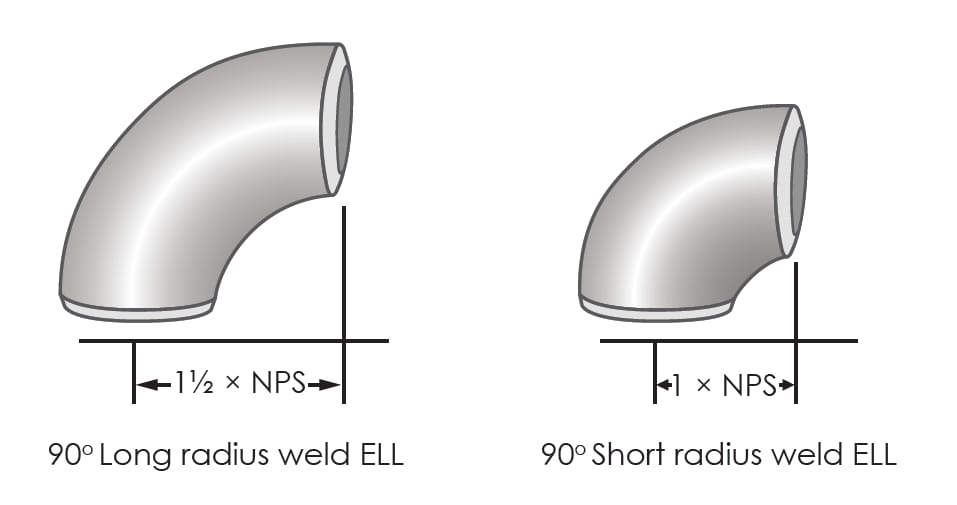
LR (Long Radius): An elbow where the center-to-end dimension is 1.5 times the nominal pipe size (NPS). This is the standard for most applications to minimize pressure drop and turbulence.
-
SR (Short Radius): An elbow with a center-to-end dimension equal to the NPS (1.0D), used in tight spaces.
-
NPS (Nominal Pipe Size): A North American standard set of sizes for pipes and fittings. For sizes NPS 12 and under, it is a nominal dimension; for NPS 14 and above, it corresponds to the actual Outside Diameter (OD).
-
OD (Outside Diameter): The actual outer diameter of the fitting ends, matching the pipe OD.
-
SCH (Schedule): The wall thickness designation for pipe and fittings (e.g., SCH 40, SCH 80).
-
CLR (Center Line Radius): The radius of the curved centerline of the elbow. For LR elbows, CLR = 1.5 x NPS (in inches).
-
Center-to-End Dimension: The fundamental dimension of an elbow. For a 90° LR elbow, this is the distance from the center of the fitting to its mating face. For a 45° LR elbow, it is the distance from the center of the end face to the centerline of the opposite end.
II. Product Classification
2.1 Classification by Angle (ASME B16.9 Standard)
We manufacture Long Radius elbows in three primary angles to suit various piping configurations:
-
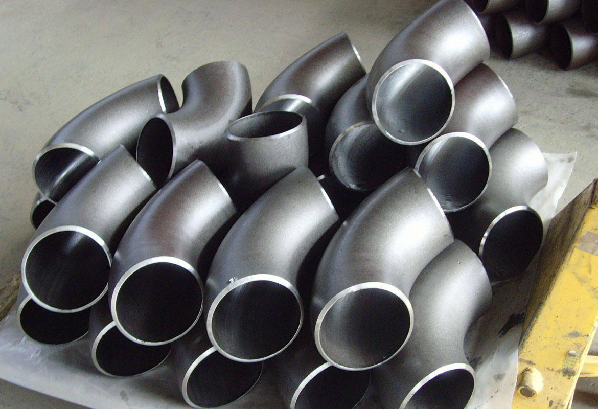
90° Long Radius Elbow: The most common type, used for 90-degree directional changes in piping systems. The 1.5D radius provides a smoother flow path than a short radius elbow, reducing erosion and pressure loss.
-
45° Long Radius Elbow: Used for gradual directional changes. This fitting is essential in systems handling high-velocity fluids or slurries where a sharp turn would cause excessive wear or turbulence. It is also common in large-diameter water lines and HVAC systems.
-
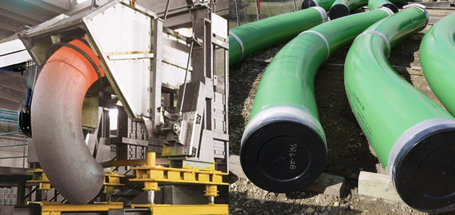
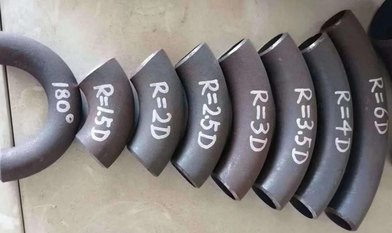
180° Long Radius Return (Return Bend): Used to reverse the direction of flow by 180 degrees. This is common in heat exchanger systems, boiler tubing, and other applications where a compact return is needed. It is defined by its center-to-center dimension.
2.2 Classification by Wall Thickness / Pressure Class
The wall thickness, or “Schedule,” determines the pressure-bearing capacity of the fitting. We offer a comprehensive range to match standard pipe schedules:
-
Thin-Wall Series: SCH 5S, SCH 10S, SCH 10 (Primarily for stainless steel in corrosive or low-pressure services, and carbon steel in non-critical applications).
-
Standard-Wall Series: SCH 20, SCH 30, SCH 40 / SCH 40S (The most common schedule for general service in carbon and stainless steel).
-
Thick-Wall / High-Pressure Series: SCH 60, SCH 80 / SCH 80S, SCH 100, SCH 120, SCH 140, SCH 160, and XXS (Double Extra Strong) . These are used in high-pressure applications such as power generation, oil & gas gathering lines, and hydraulic systems.
2.3 Classification by Manufacturing Process
-
Seamless LR Elbows: For NPS up to 24″, our fittings are typically manufactured using a seamless pipe as the starting material, which is then formed, sized, and heat-treated to achieve the required dimensions and mechanical properties.
-
Welded LR Elbows: For larger sizes (typically NPS 24 and above), we manufacture elbows using welded steel plate. The plate is rolled, seam-welded in accordance with strict procedures (e.g., ASME Section IX), formed, and sized. All welds undergo rigorous non-destructive examination to ensure integrity.
III. Core Dimensional Specifications (ASME B16.9)
All dimensions listed in the following tables are in accordance with ASME B16.9.
-
Units: Dimensions are provided in both inches and millimeters. Please note that these are nominal standard conversions as defined by the industry; for critical applications, the imperial (inch) value is the governing dimension.
- Key Dimensions:
-
A: Center-to-End dimension (for 90° and 45° elbows).
-
C: Center-to-Center dimension (for 180° returns).
-
F: End-to-End dimension (for 180° returns).
-
OD: Outside Diameter at the ends.
-
CLR: Center Line Radius (1.5 x NPS in inches).
-
3.1 90° Long Radius Elbow Dimensions (NPS 1/2 to NPS 48)
The table below details the critical dimensions for our 90° LR elbows.
| NPS | Outside Diameter (OD) | Center-to-End (A) | Center Line Radius (R) |
|---|---|---|---|
| inches / mm | inches / mm | inches (D) / mm | |
| 1/2 | 0.84 / 21.3 | 1.50 / 38.1 | 1.5 / 38.1 |
| 3/4 | 1.05 / 26.7 | 1.50 / 38.1 | 1.5 / 38.1 |
| 1 | 1.32 / 33.4 | 2.00 / 50.8 | 2.0 / 50.8 |
| 1¼ | 1.66 / 42.2 | 2.25 / 57.2 | 2.25 / 57.2 |
| 1½ | 1.90 / 48.3 | 2.50 / 63.5 | 2.5 / 63.5 |
| 2 | 2.38 / 60.3 | 3.00 / 76.2 | 3.0 / 76.2 |
| 2½ | 2.88 / 73.0 | 3.75 / 95.3 | 3.75 / 95.3 |
| 3 | 3.50 / 88.9 | 4.50 / 114.3 | 4.5 / 114.3 |
| 3½ | 4.00 / 101.6 | 5.25 / 133.4 | 5.25 / 133.4 |
| 4 | 4.50 / 114.3 | 6.00 / 152.4 | 6.0 / 152.4 |
| 5 | 5.56 / 141.3 | 7.50 / 190.5 | 7.5 / 190.5 |
| 6 | 6.62 / 168.3 | 9.00 / 228.6 | 9.0 / 228.6 |
| 8 | 8.62 / 219.1 | 12.00 / 304.8 | 12.0 / 304.8 |
| 10 | 10.75 / 273.0 | 15.00 / 381.0 | 15.0 / 381.0 |
| 12 | 12.75 / 323.8 | 18.00 / 457.2 | 18.0 / 457.2 |
| 14 | 14.00 / 355.6 | 21.00 / 533.4 | 21.0 / 533.4 |
| 16 | 16.00 / 406.4 | 24.00 / 609.6 | 24.0 / 609.6 |
| 18 | 18.00 / 457.2 | 27.00 / 685.8 | 27.0 / 685.8 |
| 20 | 20.00 / 508.0 | 30.00 / 762.0 | 30.0 / 762.0 |
| 22 | 22.00 / 558.8 | 33.00 / 838.2 | 33.0 / 838.2 |
| 24 | 24.00 / 609.6 | 36.00 / 914.4 | 36.0 / 914.4 |
| 26 | 26.00 / 660.4 | 39.00 / 990.6 | 39.0 / 990.6 |
| 28 | 28.00 / 711.2 | 42.00 / 1066.8 | 42.0 / 1066.8 |
| 30 | 30.00 / 762.0 | 45.00 / 1143.0 | 45.0 / 1143.0 |
| 32 | 32.00 / 812.8 | 48.00 / 1219.2 | 48.0 / 1219.2 |
| 34 | 34.00 / 863.6 | 51.00 / 1295.4 | 51.0 / 1295.4 |
| 36 | 36.00 / 914.4 | 54.00 / 1371.6 | 54.0 / 1371.6 |
| 38 | 38.00 / 965.2 | 57.00 / 1447.8 | 57.0 / 1447.8 |
| 40 | 40.00 / 1016.0 | 60.00 / 1524.0 | 60.0 / 1524.0 |
| 42 | 42.00 / 1066.8 | 63.00 / 1600.2 | 63.0 / 1600.2 |
| 44 | 44.00 / 1117.6 | 66.00 / 1676.4 | 66.0 / 1676.4 |
| 46 | 46.00 / 1168.4 | 69.00 / 1752.6 | 69.0 / 1752.6 |
| 48 | 48.00 / 1219.2 | 72.00 / 1828.8 | 72.0 / 1828.8 |
3.2 45° Long Radius Elbow Dimensions (NPS 1/2 to NPS 48)
The defining dimension for a 45° elbow is its center-to-end measurement, which is derived from the 90° dimension and the geometry of the bend.
| NPS | Outside Diameter (OD) | Center-to-End (B) | Center Line Radius (R) |
|---|---|---|---|
| inches / mm | inches / mm | inches (D) / mm | |
| 1/2 | 0.84 / 21.3 | 0.62 / 15.7 | 1.5 / 38.1 |
| 3/4 | 1.05 / 26.7 | 0.69 / 17.5 | 1.5 / 38.1 |
| 1 | 1.32 / 33.4 | 0.88 / 22.4 | 2.0 / 50.8 |
| 1¼ | 1.66 / 42.2 | 1.00 / 25.4 | 2.25 / 57.2 |
| 1½ | 1.90 / 48.3 | 1.13 / 28.7 | 2.5 / 63.5 |
| 2 | 2.38 / 60.3 | 1.38 / 35.1 | 3.0 / 76.2 |
| 2½ | 2.88 / 73.0 | 1.75 / 44.5 | 3.75 / 95.3 |
| 3 | 3.50 / 88.9 | 2.00 / 50.8 | 4.5 / 114.3 |
| 3½ | 4.00 / 101.6 | 2.25 / 57.2 | 5.25 / 133.4 |
| 4 | 4.50 / 114.3 | 2.50 / 63.5 | 6.0 / 152.4 |
| 5 | 5.56 / 141.3 | 3.12 / 79.2 | 7.5 / 190.5 |
| 6 | 6.62 / 168.3 | 3.75 / 95.3 | 9.0 / 228.6 |
| 8 | 8.62 / 219.1 | 5.00 / 127.0 | 12.0 / 304.8 |
| 10 | 10.75 / 273.0 | 6.25 / 158.7 | 15.0 / 381.0 |
| 12 | 12.75 / 323.8 | 7.50 / 190.5 | 18.0 / 457.2 |
| 14 | 14.00 / 355.6 | 8.75 / 222.3 | 21.0 / 533.4 |
| 16 | 16.00 / 406.4 | 10.00 / 254.0 | 24.0 / 609.6 |
| 18 | 18.00 / 457.2 | 11.25 / 285.8 | 27.0 / 685.8 |
| 20 | 20.00 / 508.0 | 12.50 / 317.5 | 30.0 / 762.0 |
| 22 | 22.00 / 558.8 | 13.75 / 349.3 | 33.0 / 838.2 |
| 24 | 24.00 / 609.6 | 15.00 / 381.0 | 36.0 / 914.4 |
| 26 | 26.00 / 660.4 | 16.25 / 412.8 | 39.0 / 990.6 |
| 28 | 28.00 / 711.2 | 17.50 / 444.5 | 42.0 / 1066.8 |
| 30 | 30.00 / 762.0 | 18.75 / 476.3 | 45.0 / 1143.0 |
| 32 | 32.00 / 812.8 | 20.00 / 508.0 | 48.0 / 1219.2 |
| 34 | 34.00 / 863.6 | 21.25 / 539.8 | 51.0 / 1295.4 |
| 36 | 36.00 / 914.4 | 22.50 / 571.5 | 54.0 / 1371.6 |
| 38 | 38.00 / 965.2 | 23.75 / 603.3 | 57.0 / 1447.8 |
| 40 | 40.00 / 1016.0 | 25.00 / 635.0 | 60.0 / 1524.0 |
| 42 | 42.00 / 1066.8 | 26.25 / 666.8 | 63.0 / 1600.2 |
| 44 | 44.00 / 1117.6 | 27.50 / 698.5 | 66.0 / 1676.4 |
| 46 | 46.00 / 1168.4 | 28.75 / 730.3 | 69.0 / 1752.6 |
| 48 | 48.00 / 1219.2 | 30.00 / 762.0 | 72.0 / 1828.8 |
3.3 180° Long Radius Return Dimensions (NPS 1/2 to NPS 24)
180° returns are defined by their Center-to-Center (C) and overall End-to-End (E) dimensions.
| NPS | Outside Diameter (OD) | Center-to-Center (C) | End-to-End (E) | Center Line Radius (R) |
|---|---|---|---|---|
| inches / mm | inches / mm | inches / mm | inches (D) / mm | |
| 1/2 | 0.84 / 21.3 | 3.00 / 76.2 | 4.50 / 114.3 | 1.5 / 38.1 |
| 3/4 | 1.05 / 26.7 | 3.00 / 76.2 | 4.50 / 114.3 | 1.5 / 38.1 |
| 1 | 1.32 / 33.4 | 4.00 / 101.6 | 6.00 / 152.4 | 2.0 / 50.8 |
| 1¼ | 1.66 / 42.2 | 4.50 / 114.3 | 6.75 / 171.5 | 2.25 / 57.2 |
| 1½ | 1.90 / 48.3 | 5.00 / 127.0 | 7.50 / 190.5 | 2.5 / 63.5 |
| 2 | 2.38 / 60.3 | 6.00 / 152.4 | 9.00 / 228.6 | 3.0 / 76.2 |
| 2½ | 2.88 / 73.0 | 7.50 / 190.5 | 11.25 / 285.8 | 3.75 / 95.3 |
| 3 | 3.50 / 88.9 | 9.00 / 228.6 | 13.50 / 342.9 | 4.5 / 114.3 |
| 3½ | 4.00 / 101.6 | 10.50 / 266.7 | 15.75 / 400.1 | 5.25 / 133.4 |
| 4 | 4.50 / 114.3 | 12.00 / 304.8 | 18.00 / 457.2 | 6.0 / 152.4 |
| 5 | 5.56 / 141.3 | 15.00 / 381.0 | 22.50 / 571.5 | 7.5 / 190.5 |
| 6 | 6.62 / 168.3 | 18.00 / 457.2 | 27.00 / 685.8 | 9.0 / 228.6 |
| 8 | 8.62 / 219.1 | 24.00 / 609.6 | 36.00 / 914.4 | 12.0 / 304.8 |
| 10 | 10.75 / 273.0 | 30.00 / 762.0 | 45.00 / 1143.0 | 15.0 / 381.0 |
| 12 | 12.75 / 323.8 | 36.00 / 914.4 | 54.00 / 1371.6 | 18.0 / 457.2 |
| 14 | 14.00 / 355.6 | 42.00 / 1066.8 | 63.00 / 1600.2 | 21.0 / 533.4 |
| 16 | 16.00 / 406.4 | 48.00 / 1219.2 | 72.00 / 1828.8 | 24.0 / 609.6 |
| 18 | 18.00 / 457.2 | 54.00 / 1371.6 | 81.00 / 2057.4 | 27.0 / 685.8 |
| 20 | 20.00 / 508.0 | 60.00 / 1524.0 | 90.00 / 2286.0 | 30.0 / 762.0 |
| 22 | 22.00 / 558.8 | 66.00 / 1676.4 | 99.00 / 2514.6 | 33.0 / 838.2 |
| 24 | 24.00 / 609.6 | 72.00 / 1828.8 | 108.00 / 2743.2 | 36.0 / 914.4 |
IV. Dimensional Tolerances (ASME B16.9 Mandatory)
Precision is paramount in buttwelding fittings. The ASME B16.9 standard defines strict tolerances to ensure proper fit-up in the field. All our products are subject to these controls.
- Outside Diameter at Bevel (OD):
- For NPS up to 24: +1.6 mm / -0.8 mm (+0.06 in / -0.03 in)
- For NPS 26 to 30: +2.4 mm / -0.8 mm (+0.09 in / -0.03 in)
- For NPS 32 to 48: +3.2 mm / -1.6 mm (+0.12 in / -0.06 in)
- Center-to-End Dimensions (A & B):
- For NPS up to 10: ±1.6 mm (±0.06 in)
- For NPS 12 to 18: ±3.2 mm (±0.12 in)
- For NPS 20 to 24: ±4.8 mm (±0.19 in)
- For NPS 26 to 30: ±6.4 mm (±0.25 in)
- For NPS 32 to 48: ±7.9 mm (±0.31 in)
-
Wall Thickness: The minimum wall thickness at any point on the fitting must be at least 87.5% of the nominal wall thickness of the specified schedule. This ensures the pressure-holding capacity is not compromised.
- Angularity Tolerances:
-
Nominal Angle (e.g., 90°): ±0.5°.
-
Cutting Plane (Squareness of ends): Max deviation is 1 mm (0.04 in) for sizes up to NPS 12, and 2 mm (0.08 in) for larger sizes.
-
-
End Preparation (ASME B16.25): The bevel angle is typically 37.5° (±2.5°) with a root face of 1.6 mm (±0.8 mm).
V. Weight Calculation and Tables
Accurate weight is crucial for logistics, structural support design, and costing. We provide theoretical weights based on geometric calculation and material density.
5.1 Weight Calculation Basis
-
Formula: The weight is derived from the volume of the fitting (calculated from its mean diameter, wall thickness, and developed length along the centerline) multiplied by the density of the material.
- Material Density Factors:
-
Carbon Steel (ASTM A234 WPB): Base Density ~7.85 g/cm³ (0.284 lb/in³). Our tables below are based on carbon steel.
-
Stainless Steel (ASTM A403 WP304/316): Multiply carbon steel weight by factor 1.02 (Density ~8.00 g/cm³).
-
Alloy Steel (ASTM A234 WP11/22): Multiply carbon steel weight by factor 1.00 – 1.01 (Density varies slightly, generally similar to carbon steel).
-
Note: The following weights are theoretical approximations. Actual weights may vary slightly due to manufacturing tolerances, slight variations in material chemistry, and the specific production batch.
5.2 90° Long Radius Elbow Weight Table (Carbon Steel, kg/piece)
*This table provides weights for the most common schedules. For other schedules or for 45°/180° weights, please consult our technical sales team.*
| NPS | SCH 10S | SCH 40S/40 | SCH 80S/80 | SCH 160 |
|---|---|---|---|---|
| 1/2 | 0.05 | 0.08 | 0.10 | 0.13 |
| 3/4 | 0.07 | 0.11 | 0.14 | 0.19 |
| 1 | 0.12 | 0.18 | 0.24 | 0.31 |
| 1¼ | 0.17 | 0.27 | 0.36 | 0.48 |
| 1½ | 0.22 | 0.36 | 0.49 | 0.65 |
| 2 | 0.35 | 0.62 | 0.85 | 1.21 |
| 2½ | 0.60 | 1.06 | 1.45 | 2.11 |
| 3 | 0.92 | 1.68 | 2.31 | 3.39 |
| 4 | 1.58 | 2.87 | 4.11 | 6.10 |
| 6 | 4.10 | 8.20 | 11.90 | 18.10 |
| 8 | 7.90 | 15.60 | 23.10 | 35.10 |
| 10 | 12.90 | 26.00 | 39.20 | 61.00 |
| 12 | 18.90 | 39.50 | 60.10 | 95.00 |
| 14 | 24.50 | 51.50 | 78.90 | 128.00 |
| 16 | 33.50 | 70.50 | 108.90 | 179.00 |
| 18 | 43.20 | 92.00 | 142.00 | 237.00 |
| 20 | 54.50 | 117.00 | 182.00 | 306.00 |
| 24 | 83.00 | 182.00 | 287.00 | 488.00 |
5.3 Weight Calculation Notes
-
For 45° LR Elbows, the approximate weight is 55% of the 90° elbow weight for the same NPS and schedule.
-
For 180° LR Returns, the approximate weight is 1.8 to 2.0 times the 90° elbow weight, depending on the size.
- For bulk orders, we recommend adding a contingency of 2-5% to the total theoretical weight for shipping calculations to account for packaging and minor variances.
VI. Material and End Preparation
-
Common Materials: We manufacture ASME B16.9 elbows from a wide range of materials to suit specific service conditions.
-
Carbon Steel: ASTM A234 WPB (most common), WPC.
-
Stainless Steel: ASTM A403 WP304/L, WP316/L, WP321, WP347.
-
Alloy Steel: ASTM A234 WP1, WP12, WP11, WP22, WP5, WP9.
-
Low-Temperature Steel: ASTM A420 WPL6, WPL3.
-
-
Buttweld End Preparation: All fittings are supplied with beveled ends conforming to ASME B16.25. This standard bevel (typically 30° to 37.5°) ensures a proper V-groove for field welding, allowing for full penetration and a strong, reliable joint. The ends are also protected with a rust-preventive coating (for carbon steel) to maintain weldability upon arrival.
-
Wall Thickness Matching: It is critical that the fitting’s schedule matches the pipe’s schedule. Our manufacturing process ensures that the fitting’s pressure rating is equivalent to, or greater than, the pipe it is designed to join.
VII. Marking and Identification
All our Long Radius elbows are permanently marked in accordance with ASME B16.9 and MSS SP-25 requirements. The markings are legible and applied using low-stress stamping to ensure traceability without damaging the product.
Typical Marking Includes:
-
Standard: ASME B16.9
-
Type: LR (Long Radius)
-
Angle: 90°, 45°, or 180°
-
Size: NPS (e.g., 6)
-
Schedule: SCH 40
-
Material Grade: A234 WPB (or equivalent)
- Manufacturer’s Name or Logo
-
Heat Number: For full traceability to material test reports.
VIII. Special Notes and Customization
-
Non-Standard Items: For applications requiring sizes larger than NPS 48, special angles, or non-standard bend radii (e.g., 3D, 5D), we offer custom fabrication. Dimensions and weights for these items are calculated on a per-order basis and are not covered by the standard tables in this document.
-
Standard Revisions: This document is a reflection of our current production capabilities aligned with the prevailing ASME B16.9 standard. Should the standard be updated with significant changes, our product specifications and this document will be revised accordingly.
-
Quality Control: Our in-house inspection utilizes calibrated Vernier calipers, height gauges, radius gauges, and welding gauges to verify all dimensions against the tolerances listed in Section IV. Any piece falling outside these tolerances is immediately rejected.
IX. Appendices
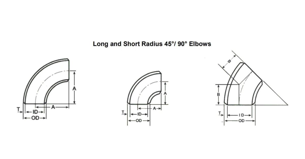
Appendix 1: Dimensional Illustration (Verbal Description)
-
90° Elbow: Imagine a quarter-circle. The straight ends are of equal length. The distance from the center of the arc’s radius to the face of one end is the ‘Center-to-End’ dimension (A). The arc itself follows a radius of 1.5 x NPS.
-
45° Elbow: This is an eighth of a circle. One end is longer than the other. The dimension from the face of one end to the centerline of the other end is the ‘B’ dimension.
-
180° Return: This forms a complete U-shape. The distance between the centerlines of the two parallel ends is the ‘C’ dimension. The total length from the outside face of one end to the outside face of the other is the ‘E’ dimension.
Appendix 2: Inch-Millimeter Unit Conversion (Reference)
| Inches | Millimeters |
|---|---|
| 1/16 | 1.59 |
| 1/8 | 3.18 |
| 1/4 | 6.35 |
| 1/2 | 12.70 |
| 1 | 25.40 |
| 2 | 50.80 |
| 6 | 152.40 |
| 12 | 304.80 |
| 36 | 914.40 |
Appendix 3: Material Density Reference (g/cm³)
| Material Type | ASTM Grade | Density (g/cm³) |
|---|---|---|
| Carbon Steel | A234 WPB | 7.85 |
| Stainless 304 | A403 WP304 | 8.00 |
| Stainless 316 | A403 WP316 | 8.00 |
| Alloy Steel | A234 WP11 | 7.86 |
| Alloy Steel | A234 WP22 | 7.83 |