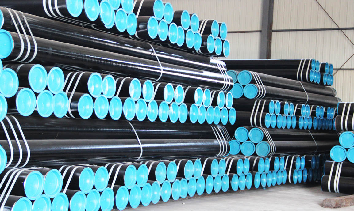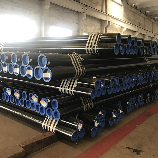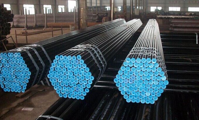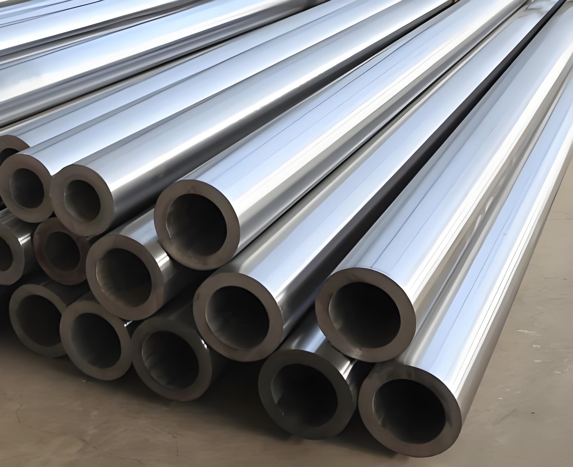
EN 10216 Seamless Steel Pipes
EN 10216 Seamless Steel Pipes for Pressure Purposes: Comprehensive Technical Specification, Metallurgical Dimensions, and Regulatory Delivery Conditions
The European Standard EN 10216 establishes the mandatory technical delivery conditions for seamless steel tubes designed specifically for pressure applications across high-temperature, low-temperature, and ambient-temperature process environments. Published by the European Committee for Standardization (CEN), this harmonized directive effectively harmonizes and supersedes older national specifications including Germany’s historical DIN 17175 and DIN 1629 frameworks. Pressure-containing equipment—such as petrochemical power plant boilers, oil refinery heat exchangers, and nuclear generation thermal networks—requires absolute geometric accuracy and verified structural metallurgy. Every single production matrix engineered under the EN 10216 framework is subjected to rigorous mechanical deformation and chemical boundary controls to fulfill these extreme industrial operating limits.
Industrial operators depend heavily on the multi-part structure of EN 10216, which is segregated logically into distinct subdivisions based on mechanical alloying methods and temperature environments. These parts comprise EN 10216-1 (Non-alloy steels with specified room temperature properties), EN 10216-2 (Non-alloy and alloy steel tubes with specified elevated temperature properties), EN 10216-3 (Alloy fine grain steel tubes), and EN 10216-4 (Non-alloy and alloy steel tubes with specified low temperature properties). Utilizing advanced autogenous manufacturing operations—ranging from piercing mills to precise cold-drawing sizing—producers achieve structural homogeneity, ensuring high resistance to circumferential hoop stresses and eliminating structural micro-fissures along the cross-sectional radius.
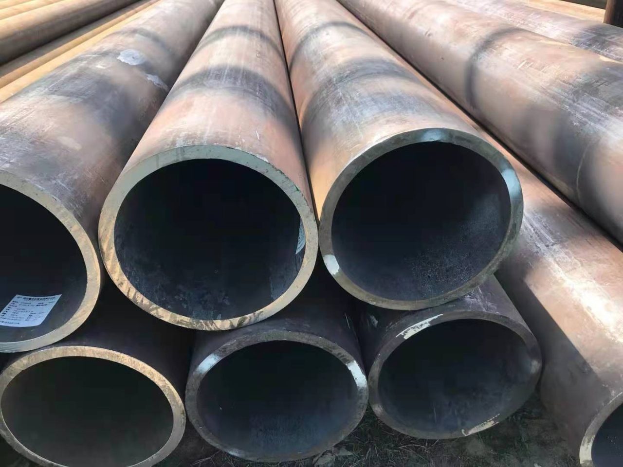
1. Master Technical Specification Envelope
To assist procurement departments, pipeline engineers, and asset managers in developing precise request-for-quote (RFQ) documentation, the master specification matrix below details the comprehensive operational boundaries and structural configurations available for EN 10216 pressure piping.
Table 1: Unified Dimensional Scope and Manufacturing Parameters
| Technical Parameter | Operational Limit & Material Capacity | Reference Unit Range |
|---|---|---|
| Outer Diameter (OD) Range | 10.2 mm to 762.0 mm (Continuous profile availability) | 1/8″ to 30″ (DN6 – DN750) |
| Wall Thickness (WT) Capacity | 0.5 mm minimum (Cold Finished) up to 130.0 mm maximum (Heavy-Wall Hot Rolled) | 0.5 mm to 130.0 mm |
| Primary Forming Disciplines | Seamless Hot Rolling (SMLSHR) or Precision Seamless Cold Drawing (SMLSCD) | Autogenous Solid Piercing |
| Structural Metallurgical Grades | P195TR1/TR2, P235TR1/TR2, P265TR1/TR2, P195GH, P235GH, P265GH, 16Mo3, 14MoV6-3, 13CrMo4-5, 10CrMo9-10, P215NL, P255QL, P265NL, 12Ni14, X10Ni9 | Carbon / Alloy / Low-Temp |
| Mandated Heat Treatment States | Full Normalizing (+N), Stress Relieving (+SR), Subcritical Annealing, or Quenching & Tempering (+QT) based on steel classification | Controlled Thermal Cycles |
| Surface Finishing Interventions | Anti-corrosion mill varnishing, blackening, transparent protective oiling, chemical pickling, or high-durability Hot-Dip Galvanizing (HDG) | Local depression depth ≤ 0.5mm |
| End-Face Preparation Types | Square Cut Plain Ends (PE), Beveled Ends for welding (BE) to ASME B16.25 (30° +5°/-0°), Threaded and Coupled (T&C), or grooved joints | Customizable Bevel Profiles |
2. Structural Machining & Secondary Fabrication Interventions
Seamless high-pressure lines must rarely be installed as straight segments. Complex mechanical environments—such as high-temperature boiler banks or multi-pass heat exchangers—require secondary machine modifications. The uniform microstructure of EN 10216 seamless tubing provides exceptional cold and hot ductility parameters, facilitating severe cross-sectional changes without triggering wall collapse or crack propagation along micro-structural grain boundaries.
Abterpipe integrates full-scale secondary fabrication processing to allow direct drop-in integration at the project site. These precision engineering methods include automated high-radius induction bending, automated branch hole drilling, hydraulic swaging, cold flaring, and pipe shoulder machining for mechanical coupling clamps. Controlled processing parameters prevent localized work-hardening, ensuring that localized pressure boundaries maintain compliance with European safety criteria.
Table 2: Authorized Pipe Processing & Joint Methods
| Machining Category | Procedural Description & Technical Execution | Primary Component Association |
|---|---|---|
| Precision Cold Bending | Rotary draw bending and high-frequency induction bending to precise center-line radii (CLR) without wall wrinkling. | Boiler Serpentine Coils |
| End Expansion / Swaging | Mechanical flaring, expanding, or conical tapering of pipe ends to allow smooth telescoping or flange collar fitting. | Tapered Fitting Connections |
| Submerged Arc Welding | Pre-fabrication of longitudinal spool networks using automated GTAW/GMAW root passes to guarantee full penetration joints. | Prefabricated Piping Spools |
| Mechanical Profiling | Radial groove cut or cold roll forming, hole punching, multi-axis drilling, and thread chasing to custom tolerances. | Coupling & Clamp Interlock |
3. Comprehensive Master Dimension Matrix: OD, WT, and Volumetric Structural Support
The dimensional envelope of EN 10216 covers a vast matrix of thickness-to-diameter ($T/D$) combinations. The master chart below serves as a data lookup framework detailing standard manufacturing profiles. A filled indicator (●) represents active, standard manufacturing availability for seamless hot-rolled and cold-finished tubes.
Table 3: Master Dimensional Availability Schedule
| Nominal OD (mm) | Wall Thickness ($T$) in Millimeters | ||||||||||||||
|---|---|---|---|---|---|---|---|---|---|---|---|---|---|---|---|
| 1.6 | 2.0 | 2.6 | 3.2 | 4.0 | 5.0 | 6.3 | 8.0 | 10.0 | 12.5 | 16.0 | 20.0 | 25.0 | 32.0 | 40.0 | |
| 10.2 | ● | ● | ● | ● | ● | — | — | — | — | — | — | — | — | — | — |
| 13.5 | ● | ● | ● | ● | ● | ● | ● | — | — | — | — | — | — | — | — |
| 17.2 | ● | ● | ● | ● | ● | ● | ● | ● | — | — | — | — | — | — | — |
| 21.3 | ● | ● | ● | ● | ● | ● | ● | ● | ● | — | — | — | — | — | — |
| 26.9 | ● | ● | ● | ● | ● | ● | ● | ● | ● | ● | — | — | — | — | — |
| 33.7 | ● | ● | ● | ● | ● | ● | ● | ● | ● | ● | ● | — | — | — | — |
| 42.4 | ● | ● | ● | ● | ● | ● | ● | ● | ● | ● | ● | ● | — | — | — |
| 48.3 | ● | ● | ● | ● | ● | ● | ● | ● | ● | ● | ● | ● | ● | — | — |
| 60.3 | ● | ● | ● | ● | ● | ● | ● | ● | ● | ● | ● | ● | ● | ● | — |
| 76.1 | ● | ● | ● | ● | ● | ● | ● | ● | ● | ● | ● | ● | ● | ● | ● |
| 88.9 | — | ● | ● | ● | ● | ● | ● | ● | ● | ● | ● | ● | ● | ● | ● |
| 114.3 | — | — | ● | ● | ● | ● | ● | ● | ● | ● | ● | ● | ● | ● | ● |
| 139.7 | — | — | — | ● | ● | ● | ● | ● | ● | ● | ● | ● | ● | ● | ● |
| 168.3 | — | — | — | — | ● | ● | ● | ● | ● | ● | ● | ● | ● | ● | ● |
| 219.1 | — | — | — | — | — | ● | ● | ● | ● | ● | ● | ● | ● | ● | ● |
| 273.0 | — | — | — | — | — | — | ● | ● | ● | ● | ● | ● | ● | ● | ● |
| 323.9 | — | — | — | — | — | — | — | ● | ● | ● | ● | ● | ● | ● | ● |
| 406.4 | — | — | — | — | — | — | — | — | ● | ● | ● | ● | ● | ● | ● |
| 508.0 | — | — | — | — | — | — | — | — | — | ● | ● | ● | ● | ● | ● |
| 610.0 | — | — | — | — | — | — | — | — | — | — | ● | ● | ● | ● | ● |
| 711.0 | — | — | — | — | — | — | — | — | — | — | — | ● | ● | ● | ● |
4. EN 10216-1: Non-Alloy Steels with Specified Ambient Temperature Properties
EN 10216-1 governs structural, fluid conveyance, and pressure-containing systems that operate under stable atmospheric temperature configurations. These pipes are widely specified for basic utility infrastructure, cross-country water distribution, chemical plant drainage networks, and low-pressure processing headers. The steel designations inside this group carry the “TR1” and “TR2” qualifiers, indicating strict divisions in test frequency and mandatory inspection criteria.
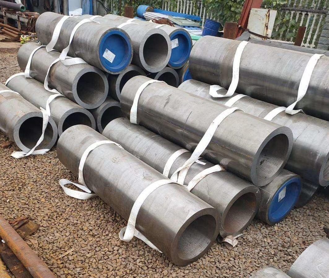
The primary operational difference centers on metallurgical verification. While TR1 grades require basic visual, dimensional, and hydrostatic validation without mandatory impact energy testing, TR2 grades enforce full batch-based Charpy V-notch impact validation and independent verification via external inspection agencies. This division protects high-risk transport networks from brittle failure mechanisms.
Table 4: EN 10216-1 Chemical Composition (Ladle Analysis, % max)
| Grade Name | Steel Number | C % | Si % | Mn % | P % | S % | Al total % | Cr+Cu+Mo+Ni |
|---|---|---|---|---|---|---|---|---|
| P195TR1 | 1.0107 | 0.13 | 0.35 | 0.70 | 0.025 | 0.020 | — | ≤ 0.70 |
| P195TR2 | 1.0108 | 0.13 | 0.35 | 0.70 | 0.025 | 0.020 | ≥ 0.020 | ≤ 0.70 |
| P235TR1 | 1.0254 | 0.16 | 0.35 | 1.20 | 0.025 | 0.020 | — | ≤ 0.70 |
| P235TR2 | 1.0255 | 0.16 | 0.35 | 1.20 | 0.025 | 0.020 | ≥ 0.020 | ≤ 0.70 |
| P265TR1 | 1.0258 | 0.20 | 0.40 | 1.40 | 0.025 | 0.020 | — | ≤ 0.70 |
| P265TR2 | 1.0259 | 0.20 | 0.40 | 1.40 | 0.025 | 0.020 | ≥ 0.020 | ≤ 0.70 |
Table 5: EN 10216-1 Mechanical Properties (Room Temperature Properties)
| Grade Name | Minimum Upper Yield Strength $R_{eH}$ (MPa) vs Wall Thickness ($T$) | Tensile Strength $R_m$ (MPa) | Minimum Elongation $A$ (%) | Charpy V-Notch Impact Energy $KV$ (J) at 0°C | ||||
|---|---|---|---|---|---|---|---|---|
| $T \le 16\text{mm}$ | $16 < T \le 40\text{mm}$ | $40 < T \le 60\text{mm}$ | Long. | Trans. | Long. | Trans. | ||
| P195TR1 | 195 | 185 | 175 | 320 to 440 | 27 | 25 | — | — |
| P195TR2 | 195 | 185 | 175 | 320 to 440 | 27 | 25 | 40 | 28 |
| P235TR1 | 235 | 225 | 215 | 360 to 500 | 25 | 23 | — | — |
| P235TR2 | 235 | 225 | 215 | 360 to 500 | 25 | 23 | 40 | 28 |
| P265TR1 | 265 | 255 | 245 | 410 to 570 | 21 | 19 | — | — |
| P265TR2 | 265 | 255 | 245 | 410 to 570 | 21 | 19 | 40 | 28 |
5. EN 10216-2: Non-Alloy and Alloy Steel Tubes for Specified Elevated Temperatures
When thermodynamic systems operate continuously at elevated thermal thresholds, they introduce serious risks of material creep deformation, graphitization, and accelerated oxidation. EN 10216-2 covers seamless circular tubes designed for critical high-temperature infrastructure, including power generating station superheaters, high-temperature chemical reactor tubes, and industrial refinery cracking furnaces.
This sub-standard includes high-purity non-alloy grades (such as P235GH and P265GH, where “GH” denotes high-temperature properties) as well as highly specialized low-alloy creep-resistant grades including 16Mo3, 13CrMo4-5, and 10CrMo9-10. Adding localized percentages of Chromium (Cr) and Molybdenum (Mo) stabilizes the steel’s microstructural carbide matrix, which prevents long-term grain-boundary sliding under high thermal and mechanical loads.
Table 6: EN 10216-2 Chemical Composition (Ladle Analysis Element Breakdown, %)
| Alloy Grade | C Range | Si Max | Mn Range | P Max | S Max | Cr Range | Mo Range | Ni Max | V Range |
|---|---|---|---|---|---|---|---|---|---|
| P195GH | ≤ 0.13 | 0.35 | ≤ 0.70 | 0.025 | 0.020 | ≤ 0.30 | ≤ 0.08 | 0.30 | ≤ 0.02 |
| P235GH | ≤ 0.16 | 0.35 | ≤ 1.20 | 0.025 | 0.020 | ≤ 0.30 | ≤ 0.08 | 0.30 | ≤ 0.02 |
| P265GH | ≤ 0.20 | 0.40 | ≤ 1.40 | 0.025 | 0.020 | ≤ 0.30 | ≤ 0.08 | 0.30 | ≤ 0.02 |
| 16Mo3 | 0.12 – 0.20 | 0.35 | 0.40 – 0.70 | 0.025 | 0.020 | ≤ 0.30 | 0.25 – 0.35 | 0.30 | — |
| 14MoV6-3 | 0.10 – 0.15 | 0.15 – 0.35 | 0.40 – 0.70 | 0.025 | 0.020 | 0.30 – 0.60 | 0.50 – 0.70 | 0.30 | 0.22 – 0.28 |
| 13CrMo4-5 | ≤ 0.15 | 0.50 – 1.00 | 0.30 – 0.60 | 0.025 | 0.020 | 1.00 – 1.50 | 0.45 – 0.65 | 0.30 | — |
| 10CrMo9-10 | 0.10 – 0.17 | 0.35 | 0.40 – 0.70 | 0.025 | 0.020 | 0.70 – 1.15 | 0.40 – 0.60 | 0.30 | — |
Table 7: EN 10216-2 Mechanical Parameter Framework
| Alloy Grade Name | Minimum Yield Strength $R_{eH}$ or $R_{p0.2}$ (MPa) | Tensile Strength $R_m$ (MPa) | Minimum Elongation $A$ (%) | Charpy V-notch Energy (J) at 20°C | ||||
|---|---|---|---|---|---|---|---|---|
| $T \le 16\text{mm}$ | $16 < T \le 40\text{mm}$ | $40 < T \le 60\text{mm}$ | Long. | Trans. | Long. | Trans. | ||
| P195GH | 195 | 185 | 175 | 320 – 440 | 27 | 25 | 40 | 27 |
| P235GH | 235 | 225 | 215 | 360 – 500 | 25 | 23 | 40 | 27 |
| P265GH | 265 | 255 | 245 | 410 – 570 | 23 | 21 | 40 | 27 |
| 16Mo3 | 280 | 270 | 260 | 450 – 600 | 22 | 20 | 40 | 27 |
| 14MoV6-3 | 320 | 320 | 310 | 460 – 610 | 20 | 18 | 40 | 27 |
| 13CrMo4-5 | 290 | 290 | 280 | 440 – 590 | 22 | 20 | 40 | 27 |
| 10CrMo9-10 | 280 | 280 | 270 | 480 – 630 | 22 | 20 | 40 | 27 |
6. Historical Standardization Cross-Reference Index (Equivalent Steel Grades)
Because many global engineering designs reference legacy European standards or modern standardizations outside Europe, cross-referencing materials is essential for global sourcing. The table below maps EN 10216-2 designations directly to older German DIN 17175 standards, British Standards (BS 3606), and equivalent international grades.
Table 8: Global Technical Equivalency Index
| Current Standard | Current Grade | Legacy German Standard | Legacy DIN Grade | British BS Equivalent |
|---|---|---|---|---|
| EN 10216-2 | P235GH | DIN 17175 | St 35.8 | HFS 360 |
| P265GH | St 45.8 | HFS 430 | ||
| 16Mo3 | 15Mo3 | BS 3606 Grade 621 | ||
| EN 10216-2 | 13CrMo4-5 | DIN 17175 | 13CrMo44 | BS 3606 Grade 620 |
| 10CrMo9-10 | 10CrMo910 | BS 3606 Grade 622 |
7. EN 10216-4: Non-Alloy and Alloy Steel Tubes for Specified Low Temperatures
Industrial processes processing liquefied gases, cryogenic chemicals, or open-air infrastructure in cold climates require materials that resist brittle fracture. As structural temperature drops below zero, standard carbon steels experience a transition from ductile to brittle behavior. EN 10216-4 addresses this issue by specifying seamless steel pipes designed for low-temperature service pressures.
To provide structural toughness at temperatures as low as -50°C, -110°C, or -196°C, EN 10216-4 defines unique alloy profiles. This sub-standard features fine-grained non-alloy options (such as P215NL and P265NL, where “NL” indicates low-temperature normalized fine grain) alongside specialized nickel-alloy structures including 12Ni14 and X10Ni9. Nickel content alters the bcc iron lattice matrix, which directly inhibits micro-crack generation under sub-zero impact challenges.
Table 9: EN 10216-4 Chemical Structural Array (% max unless ranged)
| Grade Designation | Steel ID | C % | Si % | Mn % | P % | S % | Cr % | Ni % | Al total ≥ |
|---|---|---|---|---|---|---|---|---|---|
| P215NL | 1.0451 | 0.15 | 0.35 | 0.40 – 1.20 | 0.025 | 0.020 | 0.30 | 0.30 | 0.020 |
| P255QL | 1.0452 | 0.16 | 0.35 | 0.50 – 1.40 | 0.025 | 0.020 | 0.30 | 0.30 | 0.020 |
| P265NL | 1.0453 | 0.20 | 0.40 | 0.50 – 1.40 | 0.025 | 0.020 | 0.30 | 0.30 | 0.020 |
| 26CrMo4-2 | 1.7219 | 0.22 – 0.29 | 0.40 | 0.50 – 0.80 | 0.025 | 0.020 | 0.90 – 1.20 | — | 0.020 |
| 11MnNi5-3 | 1.6212 | 0.08 – 0.14 | 0.35 | 0.70 – 1.50 | 0.025 | 0.020 | — | 0.30 – 0.85 | 0.020 |
| 12Ni14 | 1.5637 | ≤ 0.15 | 0.35 | 0.30 – 0.80 | 0.025 | 0.020 | — | 3.25 – 3.75 | 0.020 |
| X10Ni9 | 1.5682 | ≤ 0.13 | 0.35 | 0.30 – 0.80 | 0.025 | 0.020 | — | 8.50 – 9.50 | 0.020 |
Table 10: EN 10216-4 Tensile Metrics Envelope (WT ≤ 40mm)
| Grade | Minimum Proof Strength $R_{p0.2}$ (MPa) | Tensile Range $R_m$ (MPa) | Elong. $A$ Long % | Elong. $A$ Trans % |
|---|---|---|---|---|
| P215NL | 215 | 360 – 480 | 25 | 23 |
| P255QL | 255 | 360 – 490 | 23 | 21 |
| P265NL | 265 | 410 – 570 | 24 | 22 |
| 26CrMo4-2 | 440 | 560 – 740 | 18 | 16 |
| 11MnNi5-3 | 285 | 410 – 530 | 24 | 22 |
| 12Ni14 | 345 | 440 – 620 | 22 | 20 |
| X10Ni9 | 510 | 690 – 840 | 20 | 18 |
8. Sub-Zero Charpy V-Notch Mechanical Impact Energy Profile
To qualify under the EN 10216-4 directive, raw metal structures must pass standardized Charpy V-notch destructive tests per EN ISO 148-1. Testing evaluates full-size sample coupons across varying temperature levels to confirm that minimum structural energy absorption limits ($KV_2$) are maintained, preventing catastrophic pressure boundary failure.
Table 11: Mandated Impact Energy Performance Matrix
| Grade | Orientation | Minimum Average Impact Energy $KV_2$ (Joules) vs Temperature (°C) | |||||||||
|---|---|---|---|---|---|---|---|---|---|---|---|
| -196 | -120 | -110 | -100 | -90 | -60 | -50 | -40 | -20 | +20 | ||
| P215NL | Long. | — | — | — | — | — | — | 40 | 45 | 55 | — |
| Trans. | — | — | — | — | — | — | 27 | 30 | 35 | — | |
| P265NL | Long. | — | — | — | — | — | — | 40 | 45 | 50 | — |
| Trans. | — | — | — | — | — | — | 27 | 30 | 35 | — | |
| 12Ni14 | Long. | — | — | — | 40 | 45 | 50 | 55 | 55 | 60 | 65 |
| Trans. | — | — | — | 27 | 30 | 35 | 35 | 40 | 45 | 45 | |
| X12Ni5 | Long. | — | 40 | 45 | 50 | 55 | 65 | 65 | 65 | 70 | 70 |
| Trans. | — | 27 | 30 | 30 | 35 | 45 | 45 | 45 | 50 | 50 | |
| X10Ni9 | Long. | 40 | 50 | 50 | 60 | 60 | 70 | 70 | 70 | 70 | 70 |
| Trans. | 27 | 35 | 35 | 40 | 40 | 50 | 50 | 50 | 50 | 50 | |
9. Production Heat Treatment Specification Parameters
To eliminate lingering residual stresses from piercing and sizing processes, finished piping runs must undergo controlled thermal treatment. The table below lists the reference temperature boundaries and required quenching variables mandated by the EN 10216-4 delivery specification framework.
Table 12: Thermal Processing and Quenching Guidelines
| Grade Code | Delivery Condition | Normalizing Temp (°C) | Hardening/Quench (°C) | Tempering Temp (°C) |
|---|---|---|---|---|
| P215NL | Normalized (+N) | 900 to 940 | — | — |
| P255QL | Quenched & Tempered (+QT) | — | 890 to 930 (Water/Oil) | 600 to 680 |
| P265NL | Normalized (+N) | 880 to 940 | — | — |
| 26CrMo4-2 | Quenched & Tempered (+QT) | — | 830 to 860 (Water/Oil) | 600 to 680 |
| 12Ni14 | Normalized & Tempered (+NT) | 830 to 880 | — | 580 to 640 |
| X10Ni9 | Double Normalized & Tempered | 880-915 & 775-805 | — | 565 to 605 |
10. Dimensional Precision Limits & Structural Tolerances
To facilitate error-free orbital field welding and maintain uniform pressure distribution across piping networks, EN 10216 enforces strict dimensional tolerance envelopes. These controls govern outside diameter (D), wall thickness (T), and exact length configurations (L).
Table 13: Hot Finished Outside Diameter and Wall Thickness Tolerances
| Specified OD Range (D) | Permissible Tolerance on D | Permissible Tolerance on T (WT ratio) |
|---|---|---|
| $D \le 219.1\text{ mm}$ | ± 1% or ± 0.5 mm (Whichever is greater) | ± 12.5% or ± 0.4 mm (Whichever is greater) |
| $D > 219.1\text{ mm}$ | ± 1% | ± 20% (For $T/D \le 0.025$) |
| ± 15% (For $0.025 < T/D \le 0.050$) | ||
| ± 12.5% (For $0.050 < T/D \le 0.100$) | ||
| ± 10% (For $T/D > 0.100$) |
Table 14: Cold Finished Structural Profiling Tolerances
| Tolerance Type on Diameter (D) | Tolerance Type on Wall Thickness (T) |
|---|---|
| ± 0.5% or ± 0.3 mm (Whichever is greater) | ± 10% or ± 0.2 mm (Whichever is greater) |
Table 15: Exact Delivery Length Tolerances
| Specified Pipe Length Range $L$ (mm) | Permissible Length Deviation Limit (mm) |
|---|---|
| $L \le 6000$ | +10 / -0 |
| $6000 < L \le 12000$ | +15 / -0 |
| $L > 12000$ | By specific commercial agreement / -0 |
11. Test Category Structure (TC1 vs. TC2 Mandatory Inspections)
EN 10216 classifies quality assurance procedures into two separate testing categories: **Test Category 1 (TC1)** and **Test Category 2 (TC2)**. The selection depends on the severity of the operational pressure, service temperature variables, and specific regulatory demands. TC2 enforces 100% automated non-destructive testing for longitudinal imperfections, alongside mandatory product verification analysis per heat lot.
Table 16: Operational Inspection and Verification Matrix (TC1 vs TC2)
| Mandated Verification Discipline | Reference Regulation Clause | Category 1 (TC1) | Category 2 (TC2) |
|---|---|---|---|
| Chemical Cast Analysis Verification | Clause 8.2.1 | Mandatory (1/Heat) | Mandatory (1/Heat) |
| Tensile Evaluation at Room Temp | Clause 8.3.1 | Mandatory (1/Sample) | Mandatory (1/Sample) |
| Charpy V-Notch Low Temp Impact Test | Clause 8.3.2 | Optional / Excluded | Mandatory (3/Coupon) |
| Hydrostatic Pressure Leak Inspection | Clause 8.4.2 | 100% of Production | 100% of Production |
| Ultrasonic Flaw Profiling (EN ISO 10893-10) | Clause 11.11.1 | Optional / Excluded | 100% Automated Inline |
| Transverse Defect NDT (Option 5) | Clause 11.11.2 | Not Applicable | Highly Specified |
12. Hydrostatic Leak Testing Formulas and Mechanical Stress Boundaries
Every pipe produced under the EN 10216 framework must undergo internal fluid pressure validation to confirm pressure boundary integrity. The standard test pressure is capped at 7.0 MPa (~70 bar). For high-integrity configurations, the internal stress pressure ($P$) is computed using the following mathematical formula:
Where $P$ represents the calculated hydrostatic test limit metric (in MPa); $D$ represents the specified outside pipe diameter parameter (in mm); $T$ corresponds to the specified wall thickness measurement (in mm); and $S$ defines the internal stress factor (in MPa), which is restricted to 70% of the specified minimum upper yield strength characteristic for the specific steel grade.
For pipe dimensions with an outer diameter up to 457 mm, this structural pressure limit must be held for at least 5 seconds. For larger heavy-wall dimensions ($D > 457\text{ mm}$), the pressure must be held for at least 10 seconds. The entire steel structure must withstand the target pressure test without visible weeping, localized pressure drops, or wall deformation.
13. Destructive Mechanical Deformation Testing Standards
To verify structural ductility and rule out internal grain fracturing, EN 10216 requires periodic physical deformation tests on sample coupons cut from the production run. These tests evaluate tube behavior under complex mechanical loads.
Table 17: Destructive Mechanical Test Selection Guide
| Test Type | Procedural Setup and Operational Envelope | Dimensional Boundary Requirements |
|---|---|---|
| Flattening Test | Compressive flattening of a tube segment between two parallel platens until the distance between them reaches a specified threshold per EN ISO 8492. | $D < 600\text{ mm}$ and $T/D \le 0.15$ |
| Ring Tensile Evaluation | Radial expansion of a removed ring coupon using split mandrels to induce high circumferential hoop stress until fracture occurs per EN ISO 8496. | $D > 150\text{ mm}$ and $T \le 40\text{ mm}$ |
| Drift Expanding Test | Forced internal expansion of a tube end using a tapered conical mandrel to evaluate plastic strain capacity per EN ISO 8493. | $D \le 150\text{ mm}$ and $T \le 10\text{ mm}$ |
| Ring Expanding Test | Conical mandrel expansion of thin ring sections to verify cross-sectional uniform plastic strain without fracturing per EN ISO 8495. | $D \le 114.3\text{ mm}$ and $T \le 12.5\text{ mm}$ |
14. Geometric Alignment and Straightness Criteria
Straightness deviations along long piping sections introduce parasitic bending moments when networks expand thermally. EN 10216 defines strict straightness tolerances to support reliable, linear piping installations.
Table 18: Structural Straightness Deviation Parameters
| Measurement Evaluation Length Range | Maximum Permissible Deviation Limit | Verification Reference Rule |
|---|---|---|
| Total Tube Length ($L$) Span | $\le 0.0015 \cdot L$ (0.15% of total span length) | Continuous Cord Verification |
| Localized 1-Meter Gauge Interval | ≤ 3.0 mm deviation over any single meter span | Linear Dial Gauge Calibration |
15. Application Environments and Critical Processing Scenarios
Because EN 10216 covers a broad spectrum of alloy grades and structural limits, it supports many specialized applications across the high-pressure industrial sector. Selecting the appropriate sub-standard ensures long-term operational safety.
Table 19: Core Industrial Application Assignments
| Operational Target Environment | Functional Infrastructure Deployment | Recommended EN 10216 Grade |
|---|---|---|
| High-Temperature Utility Boilers | Steam headers, superheater tubes, and boiler water walls operating at high pressures and temperatures. | P235GH, P265GH, 16Mo3 |
| Petrochemical Refining Headers | High-temperature feed pipelines, heat exchangers, and catalytic cracking lines handling hydrocarbon flows. | 13CrMo4-5, 10CrMo9-10 |
| Cryogenic Utility Storage | Liquefied natural gas (LNG) headers, transport manifolds, and chilled fluid handling in sub-zero climates. | P265NL, 12Ni14, X10Ni9 |
| High-Stiffness Aerospace Elements | Precision mechanical structures requiring strict thickness uniformity and clean, seamless metal structures. | Custom Cr-Mo Alloy Profiles |
16. On-Site Logistics, Storage Protocols & Installation Alignment Criteria
Preserving the precision tolerances and surface quality of hygienic and high-pressure pipes requires careful material handling during shipping and on-site storage. To avoid galvanic contamination, stainless steel and high-alloy profiles must be stored separately from basic carbon steel components.
Pipes should be supported by wood dunnage strips or padded racks to prevent point-load deformation. Additionally, high-purity and pressure lines must be installed with a consistent slope gradient to guarantee full self-draining performance, eliminating fluid entrapment zones that could compromise system hygiene or generate localized corrosion cells during shutdown periods.
Table 20: Storage and On-Site Handling Requirements
| Handling Phase | Mandated Procedure & Protection Criteria | Target Limit Metric |
|---|---|---|
| Warehouse Storage | Store indoors on padded racks, isolated from carbon steel. Keep protective plastic end caps firmly in place to exclude airborne dust. | 100% dry environment |
| Lifting Logistics | Utilize clean nylon slings or polymer-coated hooks during transit. Never use bare steel chains or forklifts directly on stainless pipe bundles. | Zero surface scoring |
| Drainage Alignment | Horizontal runs must be pitched downward toward drain valves to ensure complete system evacuation during cleaning cycles. | Min. slope 1:100 (1%) |
17. Non-Destructive Testing (NDT) & Metallurgical Integrity Verification
To secure compliance with the strict standards governing the European petrochemical, power plant, and pipeline network matrix, every production run of EN 10216 seamless steel tubes must pass a rigorous matrix of internal non-destructive tests. These procedures guarantee structural endurance under cyclic thermal stress and eliminate risk of pinhole leakage at high process pressures.
The primary methodology deployed inline is 100% automated ultrasonic testing in full compliance with EN ISO 10893-10. This high-frequency ultrasonic testing system rapidly evaluates the continuity of the entire parent metal matrix across its full cross-sectional profile, isolating microscopic longitudinal wall fissures, internal slag inclusions, or internal cooling laminations that are invisible to the naked eye.
Table 21: Mandatory Quality Inspection Matrix and Acceptance Benchmarks
| Testing Category | Testing Methodology & Reference Regulation | Mandated Acceptance Standard |
|---|---|---|
| Ultrasonic Flaw Detection | Continuous inline full-body ultrasonic evaluation targeting longitudinal imperfections in accordance with EN ISO 10893-10. | Acceptance Level U2 Sub-category C |
| Electromagnetic Inspection | Flux leakage non-destructive evaluation of tube walls for ferromagnetic grades to uncover sub-surface inclusions per EN ISO 10893-3. | Acceptance Level F2 Limits |
| Dimensional Laser Audit | Continuous high-speed 360-degree non-contact laser telemetry to confirm nominal outside diameter uniformity and cross-sectional roundness. | Strictly inside EN 10216 envelope |
18. Post-Manufacturing Chemical Passivation & Surface Chemistry Optimization
To achieve maximum corrosion resistance within chemical process networks, finished seamless steel tubes undergo precise chemical pickling and immersion passivation treatments. This metallurgical processing removes any trace oxidation scales, mill scaling, or elemental free iron embedded on the internal and external tube walls from high-temperature hot-rolling lines.
By treating the seamless surfaces with targeted formulations of either acid blends ($HF + HNO_3$) or clear anti-corrosion oils, the underlying passive oxide barrier is stabilized. This molecular barrier layer blocks atmospheric oxidation and chemical attack from ambient moisture or aggressive process flow streams, extending pipe life in demanding environments.
Table 22: Standard Industrial Surface Treat Parameter Matrix
| Chemical Formulation | Volumetric Solution Temp. | Immersion Duration | Target Finish Quality |
|---|---|---|---|
| Acid Pickling Bath ($HNO_3/HF$) | 25°C – 40°C | 15 – 45 Minutes | Complete scale descaling |
| Hot-Dip Galvanizing ($Zn$) | 440°C – 460°C | Dip time based on WT | Coating weight ≥ 500 g/m² |
19. Regulatory Traceability & Material Certification Standards
In high-pressure and critical processing environments, material origin and metallurgical structural transparency are non-negotiable legal imperatives. All piping materials built to EN 10216 must maintain unbroken structural tracking from the primary melting furnace stage down through final cold or hot finishing sizing operations. Each lot is cross-referenced to specific mill heat numbers via permanent laser engraving or hard die-stamping along the exterior length of the pipe profile.
To secure structural sign-off from system inspection supervisors, delivery documentation must feature an official EN 10204 Type 3.1 or Type 3.2 inspection certificate. This document details actual ladle sample chemical configurations, precise mechanical breakdown metrics (including upper yield strengths $R_{eH}$, ultimate tensile limits $R_m$, and percent elongation $A$), alongside verified non-destructive testing reports and dimensional audit confirmations.
Table 23: Regulatory Traceability Framework Standards
| Regulatory Mechanism | Verification Scope & Tracking Attributes | Compliance Level |
|---|---|---|
| EN 10204 Type 3.1 Certificate | Mandatory validation listing actual physical mill mechanical results and chemical values from independent testing supervisors. | Fully Traceable Heat Tracked |
| Pressure Equipment Directive (PED) | Conforms to European Directive 2014/68/EU for fluid pressure containment across industrial equipment boundaries. | CE Certified Pressure Safe |
| Continuous Exterior Stenciling | Permanent structural surface marking stating standard reference codes, accurate dimensions, steel grade name, and primary heat code. | 100% In-field Identification |
20. CIP/SIP Protocol Compatibility & Preventive Maintenance Chemistries
Maintaining the structural wall integrity of EN 10216 seamless pressure pipelines over multi-year production campaigns requires strict adherence to standardized cleaning and maintenance regimes. Improper fluid velocities or chemical clean exposures can lead to localized erosion-corrosion or scaling deposit buildups, which degrade the internal tube volume over time.
To thoroughly clear sediment accumulation and avoid pitting corrosion, high-pressure process pipelines must sustain a minimum fluid velocity limit. Furthermore, boiler thermal flush operations utilizing superheated steam up to 350°C demand careful monitoring of thermal expansion variables to eliminate localized mechanical stress configurations along field-welded pipe elbows.
Table 24: Standard Maintenance Flush Operational Cycle Thresholds
| Operational Phase | Chemical Composition / Medium | Thermal Range | Target Kinetic Threshold |
|---|---|---|---|
| Alkaline Flush Rinse | Diluted caustic soda mixes for organic deposit descaling. | 60°C – 80°C | Min. Velocity: 1.2 m/s |
| Acid Inhibited Descaling | Formulated citric or sulfamic acid blends for scale removal. | 40°C – 55°C | Inhibitor tracking required |
| Superheated Steam Flush | Dry steam for operational line cleaning. | 150°C – 350°C | Controlled heating step rate |
21. Fluid Dynamics & Boundary Layer Mechanical Considerations
From an engineering perspective, the internal cross-sectional matrices defined by EN 10216 are optimized to control turbulent flow profiles and fluid boundary layer shear stress. When high-pressure steam or viscous liquid mixtures pass through a seamless network, the smooth internal wall design minimizes pressure friction loss and prevents internal pocket boundary separation.
Maintaining a stable turbulent flow regime (Reynolds Number $Re > 4000$) during flushing cycles is essential to prevent silt settling. Because the cross-sectional geometry of seamless profiles matches metrics pumps and standard forged fittings exactly, system engineers can minimize localized flow path adjustments, reducing turbulence-induced cavitation wear spots along pressure-boundary boundaries.
Table 25: Hydraulic Evaluation Parameters across Nominal Sizes (Carbon Steel Pipes)
| Nominal OD (mm) | Internal Diameter ($D_i$ at 4.0mm WT) | Flow Area Cross-Section | Target Volumetric Rate (at 2.0 m/s) |
|---|---|---|---|
| 48.3 mm | 40.3 mm | 1275.6 $\text{mm}^2$ | ~ 9.18 $\text{m}^3/\text{h}$ |
| 76.1 mm | 68.1 mm | 3642.3 $\text{mm}^2$ | ~ 26.22 $\text{m}^3/\text{h}$ |
| 114.3 mm | 106.3 mm | 8874.8 $\text{mm}^2$ | ~ 63.90 $\text{m}^3/\text{h}$ |
| 168.3 mm | 160.3 mm | 20185.8 $\text{mm}^2$ | ~ 145.34 $\text{m}^3/\text{h}$ |
Certification & Documentation
All EN 10216 seamless pipes supplied by Aber Steel are accompanied by:
EN 10204 Type 3.1 Mill Test Certificate (chemical analysis, mechanical properties, NDT results).
Traceability: Each pipe is stamped with heat number, grade, and dimensions.
Optional Third-Party Inspection: TÜV, BV, DNV, or client-nominated surveyor inspection available.
Additional Certifications: NORSOK M-650 compliance (for offshore service), PED 2014/68/EU conformity, and IBR (Indian Boiler Regulation) certification available for grades P235GH and P265GH.
The chemical compositions, structural parameters, and dimensional configurations in this directory comply with official European standards. Before finalizing process layouts or piping system engineering calculations, verify individual requirements against the mill-issued EN 10204 3.1 inspection certificate.