API 5L Pipe Bend & Hot Induction 3D 5D Steel Pipe Bends
Heavy Industrial Specification Manual
API 5L Pipe Bend & Hot Induction 3D 5D Steel Pipe Bends
Comprehensive Technical Datasheet: Chemical Composition, Mechanical Properties, ASME B16.49 Standards, Tolerances, and Dimensional Matrices for High-Yield Line Pipe Bends
Certified Line Pipe Fittings
1/2″ to 60″
DN15 – DN1500 Full Range
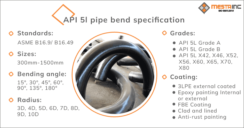
3D, 5D, 6D, 12D
Custom Radius Available
X42 to X80
PSL1, PSL2 & Sour Service
ANSI B16.49
ASME B16.25 Weld Ends
1. Executive Overview & Hot Induction Bending Technology
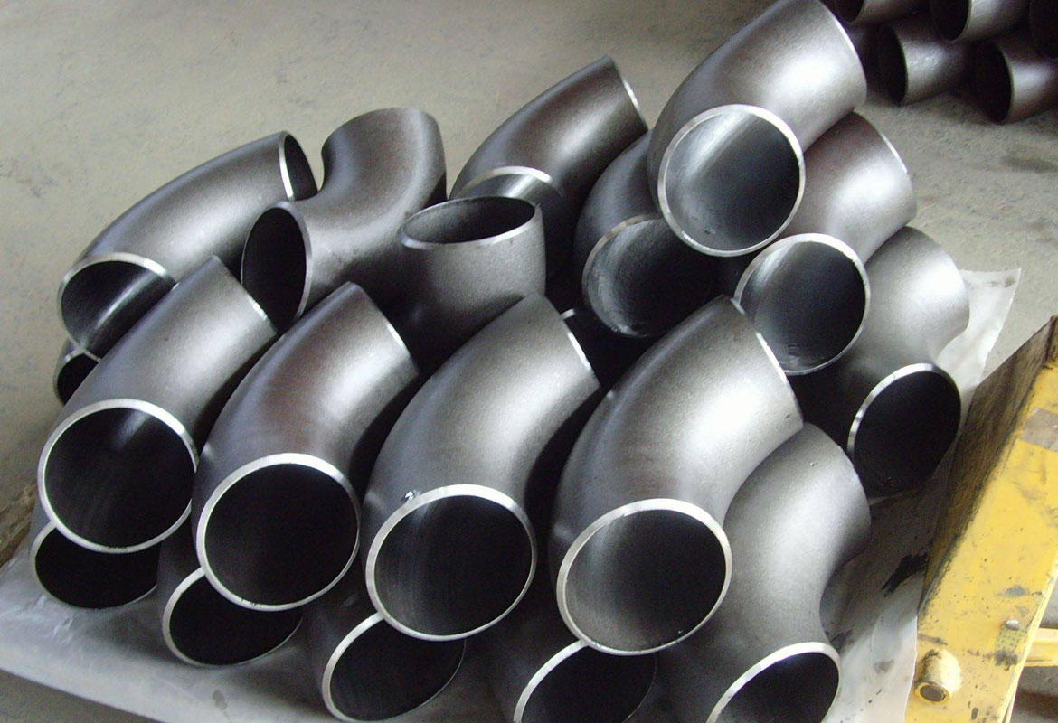
API 5L steel pipe bends are critical pressure-containing directional piping components utilized extensively across international cross-country oil, gas, water, and slurry transportation infrastructure. Unlike standard short-radius (1.0D) or long-radius (1.5D) cold-formed elbows, induction bends are manufactured using continuous medium-frequency induction heating technology. This process allows for large-radius directional shifts (typically 3D, 5D, 6D, 8D, 10D, up to 12D or custom radii) that significantly minimize friction loss, erosion-corrosion, turbulence, and fluid pressure drop inside high-pressure pipeline networks.
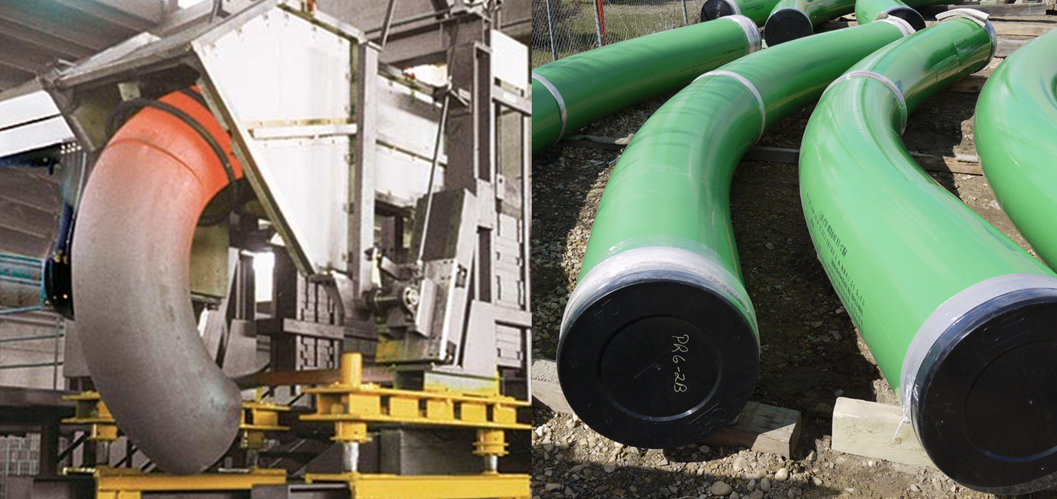
The hot induction bending technique involves passing a continuous length of seamless or welded carbon/alloy steel pipe through an electromagnetic induction heating coil. The coil heats a narrow circumferential band (360 degrees around the pipe) to elevated forging temperatures, generally between 850°C and 1050°C (1562°F to 1922°F). As the pipe is pushed forward at a constant controlled velocity by a hydraulic ram, a pivoting mechanical arm clamps the leading edge, applying a bending moment that shapes the pipe around a predetermined center-line radius (CLR). Immediately after leaving the induction coil, the heated zone is quenched using pressurized water spray, forced air, or allowed to cool in still air depending on metallurgical specifications and heat treatment requirements.
2. General Manufacturing Matrix & Supply Range
Our facility produces high-grade API 5L X42 through X80 hot induction bends engineered in strict compliance with ANSI/ASME B16.49, ISO 15590-1, and ASME B16.9 standard dimensions. Below is the master specification overview table detailing available sizes, schedules, radii, and value-added processing services.
| Parameter Class | Seamless Pipe Bend Range | Welded (LSAW / HSAW / ERW) Bend Range |
|---|---|---|
| Nominal Diameter (NPS) | 1/2″ to 24″ (DN15 – DN600) | 2″ to 60″ (DN50 – DN1500) |
| Wall Thickness / Schedule | SCH 20, SCH 40, SCH 80, SCH 120, SCH 160, SCH XXS | SCH 10 to SCH 120, WT up to 60 mm (2.36 in) |
| Centerline Bending Radii | 1.5D, 2.5D, 3D, 4D, 5D, 6D, 7D, 8D, 10D, 12D | 3D, 5D, 6D, 7D, 8D, 10D, 12D, Custom CLR up to 15m |
| Bend Angles (θ) | 11.25°, 22.5°, 30°, 45°, 60°, 90°, 180° or Custom | 11.25°, 22.5°, 30°, 45°, 60°, 90°, 180° or Custom |
| Tangent Ends Length (L1, L2) | Standard 100 mm to 500 mm or tailored to site length | Standard 150 mm to 1000 mm or extended tangent options |
| End Preparation | Beveled Ends to ASME B16.25, Plain End Square Cut | Beveled Ends (Compound Bevel / Compound Transition) |
| Surface Protection | Black Vanish, Anti-Rust Oil, FBE, 3LPE, 3LPP, Liquid Epoxy | Blast Cleaning (Sa 2.5), 3LPE Coating, Heavy FBE, Coal Tar |
| Testing Certificates | EN 10204 3.1 / 3.2, 100% UT, RT, MPI, Hydrostatic Test | EN 10204 3.1 / 3.2, 100% Weld Seam RT/UT, Hardness Map |
3. Engineering Calculations & Bend Allowance Formulas
In high-pressure pipeline design, calculating exact arc length, bend allowance, wall thinning rates, and tangent requirements is vital to prevent material starvation and excessive ovality. The mathematical models governing API 5L hot induction bends are summarized below.
Formula 1: Bend Allowance (BA) Calculation
The total arc length required to form a specified bend angle θ with centerline radius R, material thickness t, and neutral axis shift factor K is determined by:
Where: BA = Bend Allowance (mm); θ = Bend Angle (Degrees); R = Centerline Radius (mm); K = K-Factor (neutral axis position ratio, typically 0.33 to 0.50 for hot bending); t = Nominal Wall Thickness (mm).
Formula 2: Centerline Radius (CLR) Dimensional Determination
For standard nominal pipe sizes (NPS or D), the radius designation directly scales with outer diameter:
Calculation Example (6″ 5D Bend): Outer Diameter D = 6″ (152.4 mm). Centerline Radius R = 5 × 6″ = 30″ = 762.0 mm. Total Arc Length for a 90° bend = 90 × (3.14159 / 180) × 762.0 mm = 1196.9 mm (plus tangent lengths).
Formula 3: Extrados Minimum Post-Bending Wall Thickness (text)
During the bending process, the outer curve (extrados) experiences tensile strain resulting in wall thinning, while the inner curve (intrados) experiences compressive stress causing wall thickening. To satisfy ASME B31.4 / B31.8 design pressure requirements, the initial pipe wall thickness tnom must be selected so that:
Where tmin is the minimum required pipe wall thickness per line pipe design pressure calculations.
4. API 5L Grade X60 (L415) PSL1 Technical Data Profile
API 5L Grade X60 (equivalent to ISO 3183 L415) PSL1 represents standard quality high-yield seamless and welded line pipe bends designed for non-sour transportation environments. The tables below outline the chemical limit values and minimum required tensile properties.
Table 4.1: Chemical Composition for API 5L X60 PSL1 (% Mass Fraction)
| Manufacturing Type | Steel Grade | C max | Mn max | P max | S max | V max | Nb max | Ti max | Notes |
|---|---|---|---|---|---|---|---|---|---|
| Seamless Pipe | L415 or X60 | 0.28 | 1.40 | 0.030 | 0.030 | Footnote f | Footnote f | Footnote f | Cu ≤ 0.50%, Ni ≤ 0.50% |
| Welded Pipe | L415 or X60 | 0.26 | 1.40 | 0.030 | 0.030 | Footnote f | Footnote f | Footnote f | Cr ≤ 0.50%, Mo ≤ 0.15% |
Footnotes: (b) For each reduction of 0.01% below carbon max, Mn increase of 0.05% above max is permissible up to 1.75%. (c) Unless agreed, Nb + V ≤ 0.06%. (d) Nb + V + Ti ≤ 0.15%. (f) Unless agreed, Nb + V + Ti ≤ 0.001%. (g) No deliberate addition of Boron (B ≤ 0.001%).
Table 4.2: Mechanical Properties for API 5L X60 PSL1 Pipe Body & Weld Seam
| Steel Grade | Pipe Body (Seamless & Welded) | Weld Seam (EW, SAW, COW) | ||
|---|---|---|---|---|
| Yield Strength Rt0.5 (MPa / psi) min | Tensile Strength Rm (MPa / psi) min | Elongation Af (%) min | Tensile Strength Rm (MPa / psi) min | |
| L415 or X60 | 415 MPa (60,200 psi) | 520 MPa (75,400 psi) | Equation Derived (Af) | 520 MPa (75,400 psi) |
Technical Note: Minimum Elongation Calculation Equation
The specified minimum elongation (Af) in percent for API 5L bends is determined using the ISO/API empirical formula based on cross-sectional test piece area:
- C Factor: 1,940 for SI metric units (mm² / MPa) or 625,000 for USC customary units (in² / psi).
- Axc: Applicable tensile test piece cross-sectional area (mm² or in²). Standard circular cross-section pieces equal 130 mm² (0.20 in²) or 65 mm² (0.10 in²).
- U: Specified minimum ultimate tensile strength (MPa or psi). For X60, U = 520 MPa (75,400 psi).
5. API 5L Grade X60 PSL2 (L415N/Q/M) Comprehensive Data Sheet
PSL2 line pipe bends enforce stringent quality criteria, mandatory Carbon Equivalent limits, specified maximum yield strengths, notch toughness Charpy impact testing, and explicit mandatory supply delivery conditions: Normalized (N), Quenched & Tempered (Q), or Thermo-Mechanical Rolled (M).
Table 5.1: Chemical Composition for API 5L X60 PSL2 Pipe Bends
| Steel Grade | Element Mass Fraction (%) max | Carbon Equivalent max | |||||||||
|---|---|---|---|---|---|---|---|---|---|---|---|
| C | Si | Mn | P | S | V | Nb | Ti | Other | CEIIW | CEPcm | |
| L415N or X60N (SMLS) | 0.24 | 0.45 | 1.40 | 0.025 | 0.015 | 0.10 | 0.05 | 0.04 | g, h, l | As Agreed | As Agreed |
| L415Q or X60Q (SMLS) | 0.18 | 0.45 | 1.70 | 0.025 | 0.015 | g | g | g | h, l | 0.43 | 0.25 |
| L415M or X60M (Welded) | 0.12 | 0.45 | 1.60 | 0.025 | 0.015 | g | g | g | h, l | 0.43 | 0.25 |
CE Formulas: CEIIW = C + Mn/6 + (Cr+Mo+V)/5 + (Ni+Cu)/15 | CEPcm = C + Si/30 + (Mn+Cu+Cr)/20 + Ni/60 + Mo/15 + V/10 + 5B.
Table 5.2: Mechanical Properties for API 5L X60 PSL2 Hot Induction Bends
| Steel Grade | Pipe Body Requirements | Weld Seam | |||
|---|---|---|---|---|---|
| Yield Strength Rt0.5 (MPa) min / max | Tensile Strength Rm (MPa) min / max | Ratio Rt0.5 / Rm max | Elongation Af (%) min | Tensile Strength Rm (MPa) min | |
| L415N / X60N | 415 MPa (60,200 psi) min 565 MPa (81,900 psi) max |
520 MPa (75,400 psi) min 760 MPa (110,200 psi) max |
0.93 | Formula Derived | 520 MPa (75,400 psi) |
| L415Q / X60Q | |||||
| L415M / X60M | |||||
6. API 5L Grade X60 Sour Service Bends (X60QS / X60MS)
Pipeline networks conveying wet hydrogen sulfide (H2S) gas or crude oil demand specialized sour service resistant pipe bends. Sour service bends are strictly controlled to prevent Hydrogen-Induced Cracking (HIC), Sulfide Stress Cracking (SSC), and Stepwise Cracking (SWC) under NACE MR0175 / ISO 15156 compliance.
Table 6.1: Chemical Composition for API 5L X60 Sour Service (% Mass Fraction)
| Steel Grade | C max | Si max | Mn max | P max | S max | V max | Nb max | Ti max | CEIIW max | CEPcm max |
|---|---|---|---|---|---|---|---|---|---|---|
| L415QS / X60QS (SMLS) | 0.16 | 0.45 | 1.65 | 0.020 | 0.003 | 0.08 | 0.05 | 0.04 | 0.41 | 0.22 |
| L415MS / X60MS (Welded) | 0.10 | 0.45 | 1.45 | 0.020 | 0.002 | 0.08 | 0.08 | 0.06 | — | 0.21 |
Critical Sour Controls: Ultra-low Sulfur (S ≤ 0.002% for welded, 0.003% for seamless). Calcium treatment for inclusion shape control (Ca/S ≥ 1.5). Hardness limit: Maximum 22 HRC (238 HBW) across base metal, heat-affected zone (HAZ), and weld seam.
Table 6.2: Mechanical Properties for API 5L X60 Sour Service Line Pipe Bends
| Steel Grade | Yield Strength Rt0.5 (MPa) min / max | Tensile Strength Rm (MPa) min / max | Yield-to-Tensile Ratio max | Hardness Cap (HRC) | HIC / SSC Testing |
|---|---|---|---|---|---|
| L415QS / X60QS | 415 MPa (60,200 psi) min 565 MPa (81,900 psi) max |
520 MPa (75,400 psi) min 760 MPa (110,200 psi) max |
0.93 | 22 HRC (238 HBW) |
NACE TM0284 (HIC) NACE TM0177 (SSC) |
| L415MS / X60MS |
7. ASME B16.49 Factory-Made Line Pipe Bends Standard
ASME B16.49 is the definitive standard governing the design, material qualification, manufacturing processes, testing, marking, and inspection requirements for factory-made pipeline bends made from carbon and low-alloy steel materials with controlled chemistry and mechanical properties. It specifically covers induction bends for pipeline transportation and distribution piping systems compliant with ASME B31.4 (Liquid Hydrocarbons) and ASME B31.8 (Gas Transmission).
Table 7.1: ASME B16.49 Chemical Composition Limits (% Max)
| Element | Carbon [C] | Manganese [Mn] | Phosphorus [P] | Sulfur [S] | Silicon [Si] | Chromium [Cr] | Molybdenum [Mo] |
|---|---|---|---|---|---|---|---|
| Max Content (%) | 0.30 | 1.60 | 0.025 | 0.015 | 0.50 | 0.30 | 0.25 |
| Element | Vanadium [V] | Copper [Cu] | Nickel [Ni] | Niobium [Nb] | Carbon Equivalent Formula (C.E.) | ||
| Max Content (%) | 0.10 | 0.50 | 1.00 | 0.10 | C.E. = C + Mn/6 + (Cr+Mo+V)/5 + (Cu+Ni)/15 ≤ 0.45% | ||
8. ASME B16.49 Mechanical Property Grades (P241 to P552)
Under ASME B16.49, induction bends are designated by standard grade symbols matching their minimum yield strength in megapascals (MPa). The table below lists the mechanical baseline properties, hardness thresholds, and Charpy V-Notch (CVN) impact toughness values required post-bending.
Table 8.1: ASME B16.49 Designation Grades & Mechanical Baseline Matrix
| Grade Symbol | Equivalent API 5L Grade | Yield Strength min | Tensile Strength min | Elongation min | Max Hardness | Impact Test (Cv) | |||
|---|---|---|---|---|---|---|---|---|---|
| ksi | MPa | ksi | MPa | % | HBW | HRC | Joules (min avg) | ||
| P241 (X241) | Grade B / L245 | 35 | 241 | 60 | 414 | 20 | 238 | 22 | 27 J @ -20°C |
| P290 (X290) | X42 / L290 | 42 | 290 | 60 | 414 | 20 | 238 | 22 | 27 J @ -20°C |
| P317 (X317) | X46 / L320 | 46 | 317 | 63 | 434 | 20 | 238 | 22 | 27 J @ -20°C |
| P359 (X359) | X52 / L360 | 52 | 359 | 66 | 455 | 20 | 238 | 22 | 27 J @ -20°C |
| P386 (X386) | X56 / L390 | 56 | 386 | 71 | 490 | 20 | 238 | 22 | 27 J @ -20°C |
| P414 (X414) | X60 / L415 | 60 | 414 | 75 | 517 | 20 | 238 | 22 | 54 J @ -20°C |
| P448 (X448) | X65 / L450 | 65 | 448 | 77 | 531 | 18 | 238 | 22 | 54 J @ -20°C |
| P483 (X483) | X70 / L485 | 70 | 483 | 82 | 565 | 16 | 247 | 24 | 54 J @ -20°C |
| P552 (X552) | X80 / L555 | 80 | 552 | 90 | 621 | 16 | 247 | 24 | 54 J @ -20°C |
9. Post-Bending Heat Treatment Mandates
Because hot induction bending subjects the steel pipe to rapid localized thermal cycles, full post-bending heat treatment (PBHT) is mandatory to restore fine-grained microstructure, relieve residual bending stresses, and guarantee notch toughness across base metal, bend zone, and weld seams.
1. Stress Relieve / Temper
Uniformly heat the bend between 480°C (900°F) and 675°C (1250°F). Hold at temperature for at least 30 minutes per 25 mm (1 in.) of wall thickness, but no less than 30 minutes total. Air cool in still air.
2. Normalizing (N)
Heat uniformly above the upper transformation temperature (Ac3, typically 880°C–930°C). Hold for a minimum of 20 minutes per 25 mm (1 in.) of thickness, then cool freely in still air to achieve uniform ferrite-pearlite structure.
3. Quench & Temper (Q&T)
Heat above transformation temperature, hold for 20 min/25 mm, then rapidly quench in water, oil, or polymer quenchant. Reheat for high-temperature tempering (550°C–650°C) to attain optimal yield strength and impact toughness.
10. API 5L Pipe Bend Master Dimensional Data Sheet
The table below provides center-to-end (A, B) and back-to-face (O, K) dimensions for standard 3D and Long Radius (LR) pipe bends across nominal pipe sizes DN15 (1/2″) to DN400 (16″) in accordance with ASME B16.49 and ASME B16.9.
Table 10.1: Dimensional Matrix for 90°, 45° Bends and 180° Returns (mm)
| DN | NPS | Outside Dia (OD) | Center to End (90° Bend) A | Center to End (45° Bend) B | Back to Face (180° Return) O | Center to Center (180° Return) K | ||||
|---|---|---|---|---|---|---|---|---|---|---|
| 3D Bend | LR Bend | 3D Bend | LR Bend | 3D Bend | LR Bend | 3D Bend | LR Bend | |||
| 15 | 1/2″ | 21.3 | 76 | 38 | 48 | 22 | 203 | 102 | 76 | 38 |
| 20 | 3/4″ | 26.7 | 76 | 38 | 57 | 25 | 247 | 127 | 76 | 38 |
| 25 | 1″ | 33.4 | 76 | 38 | 63 | 29 | 176 | 102 | 76 | 51 |
| 32 | 1 1/4″ | 42.2 | 95 | 48 | 39 | 24 | 95 | 102 | 64 | 64 |
| 40 | 1 1/2″ | 48.3 | 114 | 57 | 47 | 29 | 114 | 127 | 76 | 76 |
| 50 | 2″ | 60.3 | 152 | 76 | 63 | 35 | 152 | 152 | 102 | 102 |
| 65 | 2 1/2″ | 73.0 | 190 | 95 | 79 | 44 | 190 | 190 | 127 | 127 |
| 80 | 3″ | 88.9 | 229 | 114 | 95 | 51 | 229 | 229 | 152 | 152 |
| 90 | 3 1/2″ | 101.6 | 267 | 133 | 111 | 57 | 267 | 267 | 178 | 178 |
| 100 | 4″ | 114.3 | 305 | 152 | 127 | 64 | 305 | 305 | 203 | 203 |
| 125 | 5″ | 141.3 | 381 | 190 | 157 | 79 | 381 | 381 | 254 | 254 |
| 150 | 6″ | 168.3 | 457 | 229 | 189 | 95 | 457 | 457 | 305 | 305 |
| 200 | 8″ | 219.1 | 610 | 305 | 252 | 127 | 610 | 610 | 406 | 406 |
| 250 | 10″ | 273.0 | 762 | 381 | 316 | 159 | 762 | 762 | 508 | 508 |
| 300 | 12″ | 323.8 | 914 | 457 | 378 | 191 | 914 | 914 | 609 | 609 |
| 350 | 14″ | 355.6 | 1067 | 533 | 441 | 222 | 1067 | 1067 | 711 | 711 |
| 400 | 16″ | 406.4 | 1219 | 610 | 505 | 254 | 1219 | 1219 | 813 | 813 |
11. High-Yield Grade Comparison (X52, X56, X60, X65, X70)
Selecting the proper steel grade for cross-country pipeline bends requires balancing operational pressure requirements, field weldability, fracture toughness, and cost effectiveness. The comparison tables below evaluate chemical limits and mechanical thresholds across the high-yield API 5L spectrum.
Table 11.1: Chemical Composition Comparison across API 5L High-Yield Bends (% Max)
| Grade | Carbon [C] | Silicon [Si] | Manganese [Mn] | Phosphorus [P] | Sulfur [S] | Vanadium [V] | Niobium [Nb] | Titanium [Ti] |
|---|---|---|---|---|---|---|---|---|
| API 5L X52 | 0.16 | 0.45 | 1.65 | 0.020 | 0.010 | 0.07 | 0.05 | 0.04 |
| API 5L X56 | 0.16 | 0.45 | 1.65 | 0.020 | 0.010 | 0.07 | 0.05 | 0.04 |
| API 5L X60 | 0.16 | 0.45 | 1.65 | 0.020 | 0.010 | 0.08 | 0.05 | 0.04 |
| API 5L X65 | 0.16 | 0.45 | 1.65 | 0.020 | 0.010 | 0.09 | 0.05 | 0.06 |
| API 5L X70 | 0.17 | 0.45 | 1.75 | 0.020 | 0.010 | 0.10 | 0.05 | 0.06 |
Table 11.2: Mechanical Property Comparison across API 5L High-Yield Bends
| Grade | Yield Strength min (KSI / MPa) | Tensile Strength min (KSI / MPa) | Yield-to-Tensile Ratio max | Elongation min (%) |
|---|---|---|---|---|
| API 5L X52 | 52 KSI / 359 MPa | 66 KSI / 455 MPa | 0.93 | 21 % |
| API 5L X56 | 56 KSI / 386 MPa | 71 KSI / 490 MPa | 0.93 | 19 % |
| API 5L X60 | 60 KSI / 414 MPa | 75 KSI / 517 MPa | 0.93 | 19 % |
| API 5L X65 | 65 KSI / 448 MPa | 77 KSI / 531 MPa | 0.93 | 18 % |
| API 5L X70 | 70 KSI / 483 MPa | 82 KSI / 565 MPa | 0.93 | 17 % |
12. Non-Destructive Examination (NDE) & Quality Control Protocols
To ensure structural integrity under severe cyclic pressure and environmental loads, 100% of manufactured hot induction bends undergo exhaustive non-destructive examination (NDE) and destructive metallurgical testing in full accordance with ASME B16.49 Clause 10 and ISO 15590-1.
| Testing Method | Standard / Specification | Acceptance Criteria & Inspection Scope |
|---|---|---|
| Ultrasonic Testing (UT) | ASTM A388 / ASME Sec V Art 4 | 100% full body wall thickness measurement post-bending; 100% shear wave UT of bend intrados/extrados and weld seam. |
| Radiographic Testing (RT) | ASME Sec V Art 2 / API 1104 | 100% X-ray examination of circumferential and longitudinal weld seams on welded pipe bends post-forming. |
| Magnetic Particle Inspection (MPI) | ASTM E709 / ASME Sec V Art 7 | 100% wet magnetic particle inspection of bevel ends, intrados, extrados, and body to detect surface/sub-surface cracks. |
| Hardness Testing & Mapping | ASTM E10 (Brinell) / ASTM E18 (Rockwell) | Grid mapping across outer radius, inner radius, neutral axis, and weld/HAZ zones. Max 238 HBW (22 HRC for sour service). |
| Charpy V-Notch (CVN) Impact | ASTM A370 / ISO 148-1 | Impact testing at -20°C (-4°F) or -46°C (-51°F). Minimum individual energy per ASME B16.49 baseline table. |
| Hydrostatic Testing | API 5L Clause 10.2 / ASME B31.8 | Test pressure maintained for minimum 10 seconds without body or seam leakage at calculated hoop stress (90% SMYS). |
13. Anti-Corrosion Protective Coating Systems
Hot induction bends placed in underground, subsea, or above-ground pipeline environments require specialized anti-corrosion coating systems capable of conforming to curved bend geometries without disbondment.
Single/Dual layer thermosetting epoxy powder coating (400–600 μm). Excellent cathodic disbondment resistance up to 110°C.
FBE primer + copolymer adhesive + outer high-density polyethylene (HDPE) sheath. Superior mechanical impact protection for buried pipe.
100% solids liquid epoxy coating applied internally and externally. Ideal for intricate bend geometries and field joints.
Black anti-rust varnish or hot-dip galvanizing compliant with ASTM A123 for industrial refinery and processing plant piping.
14. ASME B16.49 Dimensional Tolerances Summary
Tight geometric tolerances are crucial for maintaining line pipe fit-up, minimizing offset during field automatic girth welding, and avoiding stress concentration points.
Table 14.1: Permissible Geometric Variations per ASME B16.49
| Dimensional Feature | Nominal Diameter Range | Permissible Tolerance Limit |
|---|---|---|
| Bend Angle (θ) Tolerance | All Sizes (1/2″ to 60″) | ±0.5° of specified bend angle |
| Centerline Radius (CLR) Tolerance | All Sizes | ±1.0% of specified centerline radius R |
| Outside Diameter (OD) at Ends | NPS ≤ 4″ NPS 5″ to 12″ NPS ≥ 14″ |
+1.6 mm / -0.8 mm ±1.6 mm +2.4 mm / -1.6 mm |
| Ovality (Out-of-Roundness) in Bend | All Sizes | Max 3.0% [(ODmax – ODmin) / ODnom × 100] |
| End Squareness / Bevel Angle | All Sizes | Bevel angle 37.5° ± 2.5°; Root face 1.6 mm ± 0.8 mm; Off-square ≤ 1.6 mm |
| Tangent Length (L1, L2) Tolerance | All Sizes | ±5.0 mm or as agreed upon between purchaser and manufacturer |
15. Procurement Guidelines: How to Order API 5L Induction Bends
To expedite quotation and ensure flawless engineering compliance, engineering procurement contracts (EPC) should incorporate the full technical profile when requesting quotations for hot induction bends.
Standard Order Designation Example:
Essential Ordering Parameters Checklist:
- Manufacturing Standard: ASME B16.49, ISO 15590-1, or MSS-SP-75
- Steel Grade & Level: API 5L X42 to X80 (PSL1, PSL2, or Sour Service)
- Pipe Type: Seamless (SMLS) or Welded (LSAW, HSAW, ERW)
- Nominal Size & Thickness: NPS, OD (mm), Schedule or Wall Thickness (mm)
- Bend Angle & Radius: 90°, 60°, 45°, 30° (CLR = 3D, 5D, 6D, 12D)
- Tangent End Lengths: Standard or customized straight ends (L1 / L2)
- Heat Treatment Condition: Stress Relieved, Normalized, or Quenched & Tempered
- Coating & Testing: FBE, 3LPE, NACE MR0175, 100% UT/RT certification