
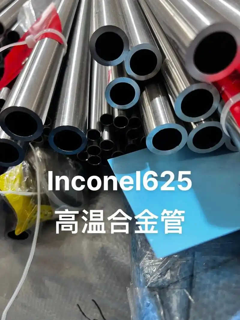
Field engineer's guide to Inconel 625 welded pipe machining. Technical parameters, tool wear analysis, and practical solutions for seamless processing of nickel alloy 625.
Field engineer's guide to Inconel 625 welded pipe machining. Technical parameters, tool wear analysis, and practical solutions for seamless processing of nickel alloy 625.
Summary of Core Process Links Summary of Intermediate Frequency and High Frequency Heat Expansion Process Comparison Summary of Internship Gains and Existing Problems Overall Summary of the Process
Core Principle and Technical Analysis of Heat-Expanded Seamless Steel Pipe Process
Core Principle and Technical Analysis of Medium and High Frequency Heat-Expanded Seamless Steel Pipe Process
As an undergraduate majoring in Pipeline Industry, mastering the core principle and technical points of the Guanzhong medium and high frequency heat-expanded seamless steel pipe process is the foundation of learning this major well, and also a necessary skill for engaging in work related to the pipeline industry in the future. During the course study and internship, I have conducted in-depth research and practice on the core principle, technical characteristics, key links and parameter control of this process. Combined with my personal understanding and internship experience, the following is a detailed elaboration of these contents, which will integrate some specific problems and solutions I encountered during the internship, making the technical analysis closer to actual production.
3.1 Core Principle of the Process
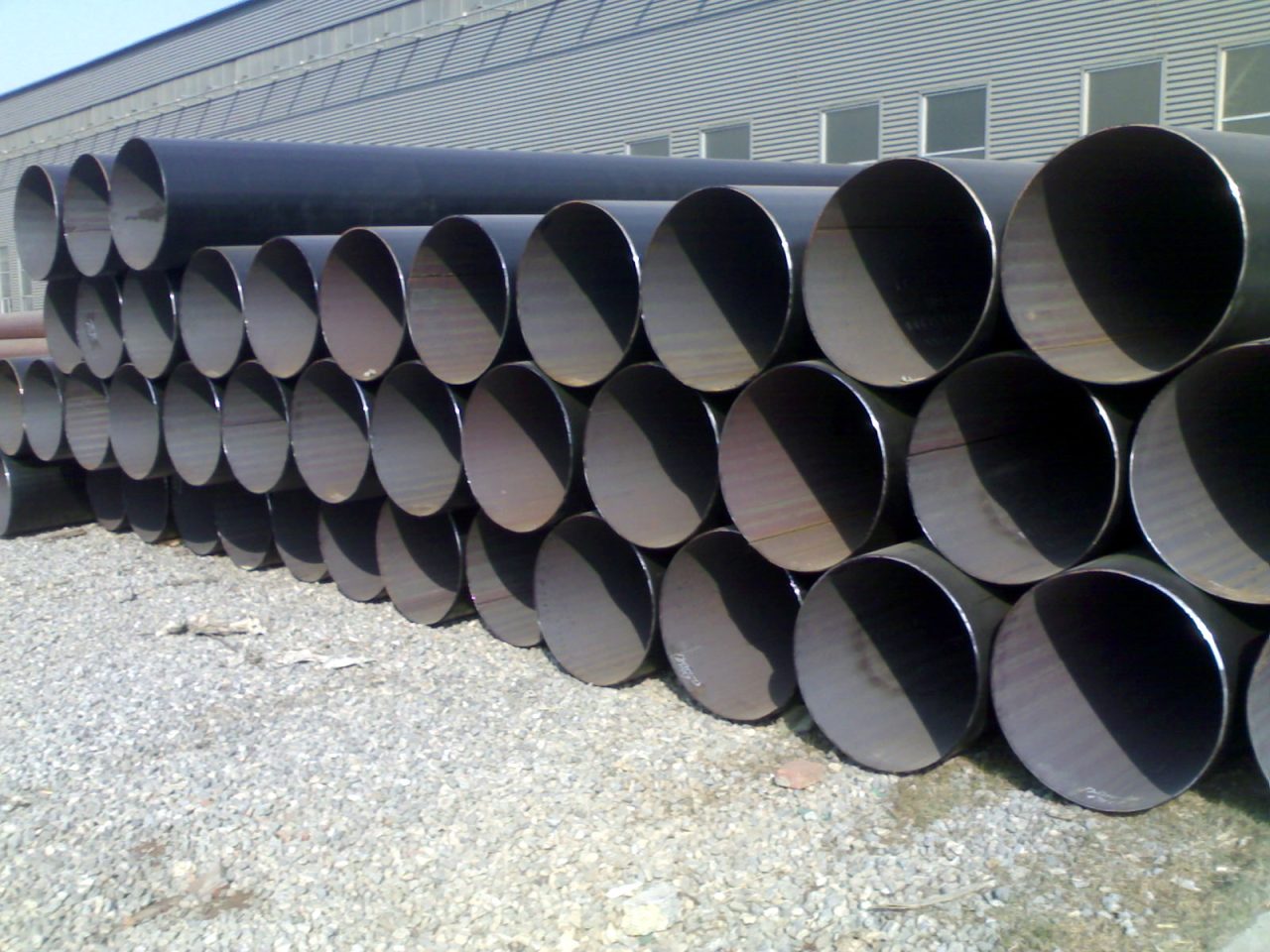
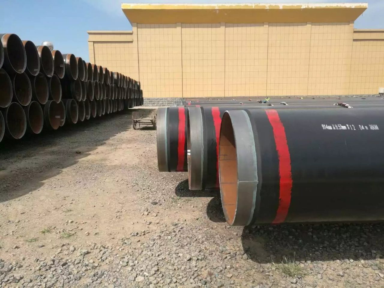
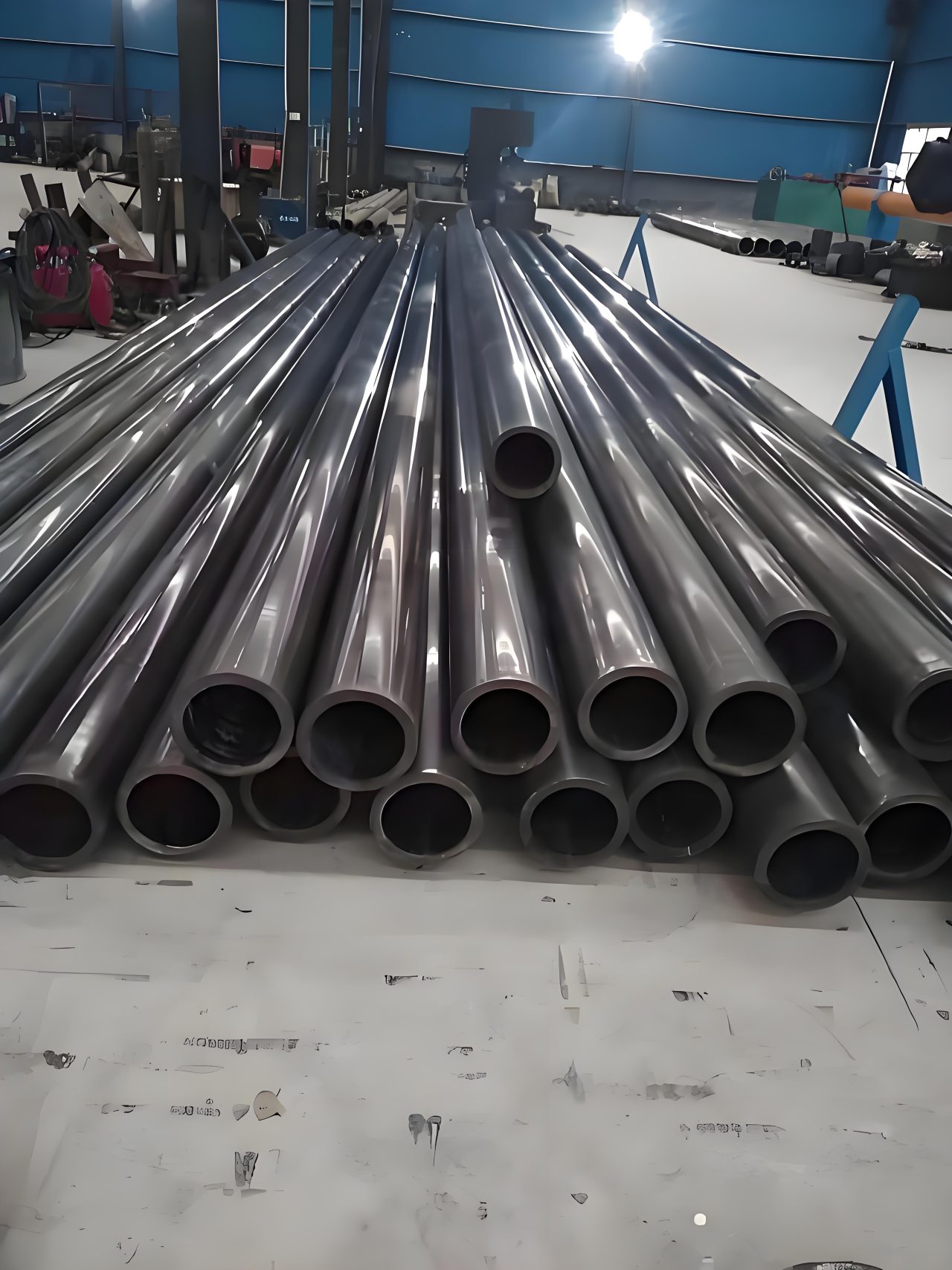
The Guanzhong medium and high frequency heat-expanded seamless steel pipe process is essentially a secondary thermal processing process for seamless steel pipes (mother pipes). Its core principle is: using the electromagnetic induction effect generated by intermediate frequency or high frequency current, the mother pipe is heated to the plastic deformation temperature range, and then under the support of the plug and the action of external force, the mother pipe undergoes radial expansion and axial extension, so as to obtain a seamless steel pipe (finished pipe) with larger diameter and thinner wall thickness, while ensuring that the dimensional accuracy, surface quality and mechanical properties of the finished pipe meet the engineering requirements.
Here I want to emphasize that many people are easy to confuse the Guanzhong medium and high frequency heat expansion process with the hot-rolled seamless steel pipe process. In fact, there are great differences between the two. Hot-rolled seamless steel pipes are directly rolled from steel billets without the need for mother pipes, while the Guanzhong medium and high frequency heat expansion process is a secondary processing of formed seamless steel pipes, which requires mother pipes as raw materials; the hot-rolled process is suitable for producing small and medium-diameter, thick-walled seamless steel pipes, while the heat expansion process is suitable for producing large-diameter, medium-thin-walled seamless steel pipes; moreover, the equipment investment of the heat expansion process is much lower than that of the hot-rolled process, and the production flexibility is stronger. It can quickly adjust product specifications according to market demand and produce steel pipes of different diameters and wall thicknesses. During the internship, I often saw the workshop produce finished pipes of different specifications by adjusting process parameters with mother pipes of different specifications according to customer orders. Sometimes, several different specifications of products can be produced in one day, which is the advantage of the heat expansion process.
Specifically, the core principle of the Guanzhong medium and high frequency heat expansion process can be divided into two parts: electromagnetic induction heating principle and plastic deformation principle.
The electromagnetic induction heating principle is the foundation of the Guanzhong medium and high frequency heat expansion process. When intermediate frequency and high frequency current pass through the induction coil, an alternating magnetic field will be generated. When the mother pipe is in the alternating magnetic field, an induced current (eddy current) will be generated inside the mother pipe. When the eddy current flows inside the mother pipe, it will be hindered by the resistance of the mother pipe itself, thus generating Joule heat and heating the mother pipe quickly. It should be noted here that the difference between intermediate frequency and high frequency mainly lies in the difference of current frequency: the frequency of intermediate frequency current is generally 1-10kHz, and the frequency of high frequency current is generally 10-50kHz. Different frequencies of current produce different electromagnetic induction effects and heating effects. Intermediate frequency heating is characterized by deep heating depth and uniform temperature, which is suitable for heating large-diameter and thick-walled mother pipes; high frequency heating is characterized by fast heating speed and small heat-affected zone, which is suitable for heating small-diameter and thin-walled mother pipes. This is the reason why the intermediate frequency and high frequency heat expansion processes complement each other as I mentioned earlier.
The principle of plastic deformation is the core of the Guanzhong medium and high frequency heat expansion process. When the mother pipe is heated to the plastic deformation temperature range (for ordinary carbon steel, generally 900-1100℃), the metal structure of the mother pipe will change, the grains will be refined, the plasticity will be significantly improved, and the brittleness will be reduced. At this time, under the support of the plug and the external force (expansion pressure), the mother pipe will undergo plastic deformation, radial expansion and axial extension, and finally form the finished pipe that meets the requirements. In this process, it is necessary to strictly control the heating temperature and deformation speed. If the heating temperature is too high, it will lead to serious oxidation of the mother pipe surface, coarse grains, and affect the mechanical properties of the finished pipe; if the heating temperature is too low, the plasticity of the mother pipe is insufficient, which is easy to break and cannot complete the expansion; if the deformation speed is too fast, it will lead to low dimensional accuracy and excessive wall thickness deviation of the finished pipe; if the deformation speed is too slow, it will reduce production efficiency and increase energy consumption.
During the internship, I encountered such a problem: once, the workshop produced DN800 finished pipes. Due to the carelessness of the operator, the temperature of the intermediate frequency heating furnace was adjusted to 1150℃, which exceeded the specified maximum temperature, resulting in excessive heating of the mother pipe, serious surface oxidation. Moreover, after expansion, the grains of the finished pipe were coarse, the mechanical performance test was unqualified, and it could only be scrapped. This incident also made me deeply realize the importance of process parameter control. Even a small parameter deviation may lead to product scrapping and economic losses.
3.2 Comparison and Technical Characteristics of Intermediate Frequency and High Frequency Heat Expansion Processes
Intermediate frequency heat expansion and high frequency heat expansion are two main forms of the Guanzhong medium and high frequency heat-expanded seamless steel pipe process. Both are based on the electromagnetic induction heating principle and plastic deformation principle, but due to the different current frequencies, there are obvious differences between the two in heating effect, technical characteristics, application scope and other aspects. During the internship, I stayed in the intermediate frequency heat expansion workshop and high frequency heat expansion workshop for a period of time, and had an intuitive understanding of the differences between the two processes. Combined with my personal practical experience, the following is a detailed comparative analysis of the two processes, as shown in Table 1.
| Comparison Items | Intermediate Frequency Heat Expansion Process (1-10kHz) | High Frequency Heat Expansion Process (10-50kHz) |
| Heating Principle | Eddy current generated by electromagnetic induction, deep heating depth, uniform temperature, large heat-affected zone | Eddy current generated by electromagnetic induction, fast heating speed, small heat-affected zone, mainly heating the surface |
| Heating Efficiency | Medium, generally 65%-75%, suitable for batch heating | High, generally 75%-85%, heating speed is 2-3 times faster than intermediate frequency |
| Applicable Mother Pipe Specifications | Large-diameter, thick-walled mother pipes (DN200-DN1500, wall thickness 8-30mm), such as DN300 and DN500 mother pipes commonly used during my internship | Small-diameter, thin-walled mother pipes (DN50-DN300, wall thickness 3-10mm) |
| Characteristics of Finished Pipes | Large diameter, uniform wall thickness, medium dimensional accuracy, general surface quality, stable mechanical properties, more oxide scale | Small diameter, thin wall thickness, high dimensional accuracy, good surface quality, less oxide scale, better mechanical properties |
| Production Efficiency | Medium, long heating time for single steel pipe (5-15min), suitable for mass production of large-diameter products | High, short heating time for single steel pipe (1-5min), suitable for mass production of small-diameter products |
| Energy Consumption Level | High, unit energy consumption 650-800kWh/ton of steel pipe, reduced to 650kWh/ton after the enterprise I interned in upgraded | Low, unit energy consumption 500-650kWh/ton of steel pipe |
| Equipment Investment | Large, high investment in intermediate frequency heating furnace, expansion equipment, etc., about 5-10 million yuan for one production line | Small, high-frequency heating furnace is small in size and low in cost, about 2-5 million yuan for one production line |
| Applicable Fields | Large-diameter transmission pipelines in petroleum chemical industry, municipal pipe network, energy power and other fields, such as central heating pipe network in Shaanxi region | Small-diameter precision pipelines in precision machinery, small chemical industry, medical equipment and other fields |
| Core Advantages | Strong production flexibility, can produce large-diameter and thick-walled finished pipes, stable mechanical properties, suitable for large-scale mass production | Fast heating speed, low energy consumption, high dimensional accuracy and good surface quality of finished pipes, suitable for precision product production |
| Existing Shortcomings | High energy consumption, general surface quality, more oxide scale, need subsequent finishing treatment; early excluded from the high-pressure boiler standard | Cannot produce large-diameter and thick-walled finished pipes, limited equipment power, insufficient heating depth |
Table 1 Comparison Table of Intermediate Frequency and High Frequency Heat Expansion Processes
From the above comparison, we can clearly see that the intermediate frequency heat expansion and high frequency heat expansion processes have their own advantages and disadvantages. They are not alternative to each other, but complementary, forming the Guanzhong medium and high frequency heat-expanded seamless steel pipe process system together. In actual production, enterprises will choose the appropriate heat expansion process according to market demand, product specifications, customer requirements and other factors. For example, the enterprise I interned in mainly produces large-diameter heat-expanded seamless steel pipes, so it mainly adopts the intermediate frequency heat expansion process and is equipped with two intermediate frequency heat expansion production lines; while a small steel pipe enterprise next to it mainly produces small-diameter precision steel pipes, so it adopts the high frequency heat expansion process and is equipped with three high frequency heat expansion production lines.
In addition, during the internship, I also found that with the continuous upgrading of technology, the boundary between intermediate frequency and high frequency heat expansion processes is gradually blurring. For example, some enterprises have realized precise surface temperature control of the intermediate frequency heat expansion process by optimizing the structure of the induction coil and improving the heating method, reducing the generation of oxide scale and improving the surface quality of the finished pipe; while some enterprises have realized deep heating of the high frequency heat expansion process by increasing the power of the high frequency equipment, which can produce finished pipes with larger diameter and thicker wall thickness. This trend of technological integration has also become one of the important development directions of the Guanzhong medium and high frequency heat expansion process. At the same time, both intermediate frequency and high frequency heat expansion pay more and more attention to the control of pipe blank quality and deformation zone temperature. By reasonably selecting deformation parameters and strengthening finished product inspection, the product quality is ensured to meet the standard requirements.
3.3 Key Process Links and Technical Control Points
The production process of the Guanzhong medium and high frequency heat-expanded seamless steel pipe process mainly includes seven core links: raw material inspection, mother pipe pretreatment, induction heating, expansion forming, cooling, finishing and finished product inspection. Each link has its key technical control points. Any problem in any link will affect the quality of the finished pipe. During the internship, I participated in the work of these seven links and had a deep understanding of the technical control points of each link. Combined with my personal practical experience, the following is a detailed elaboration of the key technical control points of each link, which will integrate some problems and solutions I encountered during the internship, making the technical analysis closer to actual production.
3.3.1 Raw Material Inspection
Raw material inspection is the first line of defense of the Guanzhong medium and high frequency heat expansion process, and also the foundation to ensure the quality of finished pipes. The raw material of the Guanzhong medium and high frequency heat expansion process is seamless steel pipe (mother pipe). The quality of the mother pipe directly determines the quality of the finished pipe. If the mother pipe has defects such as cracks, inclusions and excessive wall thickness deviation, even if the subsequent process parameters are well controlled, it is impossible to produce qualified finished pipes. During the internship, my first post was raw material inspection. My daily work was to inspect the incoming mother pipes. The main inspection items included: specification model, material, wall thickness deviation, surface quality and mechanical properties of the mother pipe.
Specifically, there are three key technical control points for raw material inspection: first, material inspection. It is necessary to ensure that the material of the mother pipe meets the production requirements. For example, to produce Q355 heat-expanded seamless steel pipes, the material of the mother pipe must also be Q355, and Q235 mother pipes cannot be used instead, otherwise the mechanical properties of the finished pipe will be unqualified. During the internship, I encountered a case of inconsistent material: a batch of incoming mother pipes was marked as Q355, but after spectral analysis, it was found that the actual material was Q235, which did not meet the production requirements. We returned this batch of mother pipes to the supplier in time to avoid quality problems in subsequent production. Second, wall thickness deviation inspection. The wall thickness deviation of the mother pipe must be controlled within the allowable range (generally ±5%). If the wall thickness deviation of the mother pipe is too large, the wall thickness deviation of the finished pipe after expansion will also be too large, which cannot meet the engineering requirements. We used ultrasonic thickness gauges to measure multiple points at different parts of the mother pipe to ensure uniform wall thickness. Third, surface quality inspection. It is necessary to check whether the surface of the mother pipe has defects such as cracks, scratches, oxide scale and inclusions. If there are these defects, it needs to be polished. It can enter the next process only after passing the treatment; if the defects are too serious to be treated, it needs to be scrapped. For example, once, we found that the surface of a batch of mother pipes had many scratches with depth exceeding 0.5mm. After polishing, they still could not be eliminated, so this batch of mother pipes had to be scrapped.
Here I want to emphasize that the raw material inspection link must not be careless. Many enterprises have produced a large number of unqualified products and caused huge economic losses because they ignored the raw material inspection. The enterprise I interned in has very strict requirements on raw material inspection, established a complete raw material inspection system. Each batch of incoming mother pipes must be inspected, and can be put into storage only after passing the inspection. Moreover, the inspection records must be retained throughout the process to facilitate subsequent quality traceability. At the same time, for mother pipes used in high-end products, electric arc furnace, LF refining and VD vacuum degassing triple process will also be adopted to ensure the purity of molten steel, control the S and P content below 0.015%, and lay a good foundation for the subsequent heat expansion process.
3.3.2 Mother Pipe Pretreatment
Mother pipe pretreatment is an important link of the Guanzhong medium and high frequency heat expansion process. Its purpose is to remove impurities such as oxide scale, oil stain and rust on the surface of the mother pipe, adjust the dimensional accuracy of the mother pipe, and prepare for subsequent induction heating and expansion forming. The quality of mother pipe pretreatment directly affects the effect of induction heating and the surface quality of the finished pipe. If there are oil stains, rust and other impurities on the surface of the mother pipe, the heating will be uneven during heating, and the impurities will adhere to the surface of the finished pipe, affecting the surface quality; if the dimensional accuracy of the mother pipe does not meet the requirements, the dimensional accuracy of the finished pipe after expansion will also be affected.
Mother pipe pretreatment mainly includes three steps: polishing, straightening and degreasing. Each step has its key technical control points. First, polishing. It is mainly to remove oxide scale, rust and scratches on the surface of the mother pipe. The surface of the polished mother pipe should be smooth and flat without obvious defects, and the surface roughness should be controlled at Ra≤12.5μm. We used automatic polishing machines at that time, the polishing speed was controlled at 10-15m/min, and the polishing pressure was controlled at 0.3-0.5MPa to ensure the polishing effect. If the oxide scale on the surface of the mother pipe is thick, it needs to be sandblasted first, then polished. Second, straightening. It is mainly to adjust the straightness of the mother pipe to ensure that the straightness of the mother pipe meets the requirements (straightness deviation per meter ≤1mm). If the mother pipe is bent, the force will be uneven during expansion, and the finished pipe will have problems such as ellipse and excessive wall thickness deviation. We used a hydraulic straightener, the straightening pressure was controlled at 10-20MPa. The straightened mother pipe should be tested for straightness, and the unqualified ones should be straightened again. Third, degreasing. It is mainly to remove oil stains on the surface of the mother pipe. Oil stains will affect the effect of induction heating, and harmful gases will be generated during heating, polluting the environment. We used alkaline degreasing agent, the degreasing temperature was controlled at 50-60℃, the degreasing time was controlled at 10-15min. After degreasing, the mother pipe should be washed with water to remove the residual degreasing agent on the surface, then dried to ensure that the surface of the mother pipe is dry and free of moisture.
During the internship, due to carelessness, I sent a mother pipe to the heating furnace without thorough degreasing treatment. As a result, during heating, the oil stains on the surface of the mother pipe burned, producing a lot of black smoke, which not only polluted the environment, but also caused uneven heating of the mother pipe. After expansion, many black spots appeared on the surface of the finished pipe, which could only be scrapped. This incident made me deeply realize that every step of the mother pipe pretreatment link must be operated in strict accordance with the requirements, and there can be no slightest carelessness. At the same time, for products that need overall heat treatment after expansion, the quality of mother pipe pretreatment will also affect the heat treatment effect, and then affect the mechanical properties of the finished pipe.
3.3.3 Induction Heating
Induction heating is the core link of the Guanzhong medium and high frequency heat expansion process, and also the link with the greatest difficulty in technical control. Its core task is to heat the mother pipe to the plastic deformation temperature range, and ensure uniform heating and stable temperature, so as to provide good plastic conditions for subsequent expansion forming. The quality of induction heating directly determines the mechanical properties, dimensional accuracy and surface quality of the finished pipe, and is the “soul” of the entire process. During the internship, I spent a long time learning the operation and parameter control of the induction heating link, followed the workshop master to learn how to adjust the heating power, heating time, how to control the heating temperature, and accumulated a lot of valuable practical experience.
The key technical control points of induction heating are mainly three: first, heating temperature control, second, heating speed control, third, temperature uniformity control.
Heating temperature control is the core of the induction heating link. Different materials of mother pipes have different plastic deformation temperature ranges, which must be strictly controlled within the corresponding temperature range, not too high or too low. For example, the plastic deformation temperature range of ordinary carbon steel (20#, Q235) is 900-1100℃, that of Q355 high-strength steel is 950-1150℃, and that of 304 stainless steel is 1050-1200℃. If the heating temperature is too high, it will lead to serious oxidation of the mother pipe surface, coarse grains, even burnout, affecting the mechanical properties and surface quality of the finished pipe; if the heating temperature is too low, the plasticity of the mother pipe is insufficient, which is easy to break and cannot complete the expansion. During the internship, we used infrared thermometers to monitor the surface temperature of the mother pipe in real time, and measured the internal temperature of the mother pipe with thermocouples every 5 minutes to ensure that the temperature was controlled within the specified range. At the same time, for the intermediate frequency induction heating push-type process, although it is local heating, the intelligent temperature control system can effectively ensure the stable temperature of the deformation zone and avoid the adverse impact of temperature fluctuation on the expansion deformation.
Heating speed control is also very important. If the heating speed is too fast, it will lead to too high surface temperature and too low internal temperature of the mother pipe, resulting in the phenomenon of “burned outside but raw inside” and poor temperature uniformity; if the heating speed is too slow, it will reduce production efficiency, increase energy consumption, and lead to too much oxide scale on the mother pipe surface. Generally speaking, the heating speed of intermediate frequency heat expansion is controlled at 50-100℃/min, and that of high frequency heat expansion is controlled at 100-200℃/min. The heating speed of mother pipes of different specifications and materials needs to be adjusted appropriately. For example, the heating speed of large-diameter and thick-walled mother pipes should be slower to ensure sufficient internal heating; the heating speed of small-diameter and thin-walled mother pipes can be faster to improve production efficiency. During the internship, I once caused a DN500, 15mm wall thickness mother pipe to appear the phenomenon of “burned outside but raw inside” due to too fast heating speed. The surface temperature reached 1150℃, but the internal temperature was only 850℃, which could not be expanded and had to be reheated, which not only wasted electric energy, but also delayed the production progress.
Temperature uniformity control is another key point of the induction heating link. The temperature of the mother pipe must be uniform, and there should be no local overheating or local low temperature. Otherwise, during expansion, the plastic deformation of the mother pipe will be uneven, leading to defects such as ellipse, excessive wall thickness deviation and surface cracks of the finished pipe. To ensure temperature uniformity, we mainly took three measures: first, optimize the structure of the induction coil. According to the specification of the mother pipe, design a suitable induction coil to ensure uniform gap between the coil and the mother pipe (generally 5-10mm); second, adopt segmental heating method, divide the mother pipe into multiple heating segments, and control the temperature of each heating segment respectively to ensure uniform overall temperature; third, drive the mother pipe to rotate through mechanical devices during heating, so that all parts of the mother pipe can be heated uniformly. During the internship, I once encountered the problem of uneven temperature of the mother pipe. The temperature of one side of a mother pipe reached 1050℃, while the temperature of the other side was only 950℃. After expansion, the finished pipe appeared obvious ellipse, and the wall thickness deviation exceeded the allowable range, which could only be scrapped. Later, we found that it was caused by the uneven gap between the induction coil and the mother pipe. After adjusting the gap, the temperature uniformity was significantly improved. At the same time, for the intermediate frequency heat expansion process, the temperature uniformity can also be effectively improved by adjusting the distribution of heating power, ensuring stable expansion deformation.
3.3.4 Expansion Forming
Expansion forming is the core forming link of the Guanzhong medium and high frequency heat expansion process. Its purpose is to make the mother pipe undergo radial expansion and axial extension under the support of the plug and the action of external force when it is in the plastic deformation state, so as to obtain the required finished pipe specifications. The quality of expansion forming directly determines the dimensional accuracy, wall thickness deviation and shape accuracy of the finished pipe, and is one of the key links of the entire process. During the internship, I followed the workshop master to learn the operation of the expansion forming link, understood the working principle and parameter control points of the expansion equipment, and personally participated in the auxiliary work of expansion forming.
The key technical control points of expansion forming are mainly four: first, plug selection, second, expansion speed control, third, expansion pressure control, fourth, expansion ratio control.
Plug selection is the foundation of expansion forming. The material, shape and size of the plug must match the specification and material of the mother pipe. The material of the plug is generally high-temperature resistant and high-strength alloy materials, such as H13 die steel and 3Cr2W8V alloy steel, which can withstand the action of high temperature and high pressure and avoid plug deformation or damage. The shape of the plug is mainly conical plug and spherical plug. The conical plug is suitable for expansion of large-diameter and thick-walled mother pipes, and the spherical plug is suitable for expansion of small-diameter and thin-walled mother pipes. The size of the plug should be designed according to the specification of the finished pipe to ensure that the diameter of the finished pipe after expansion meets the requirements. During the internship, I once selected the wrong plug size, resulting in the diameter of a DN800 finished pipe being too small to meet the customer’s requirements, so it had to be expanded again, wasting manpower and material resources. At the same time, the surface of the plug should be smooth to avoid scratching the inner surface of the mother pipe and affecting the inner surface quality of the finished pipe.
Expansion speed control is the core of expansion forming. If the expansion speed is too fast, it will lead to uneven plastic deformation of the mother pipe, resulting in defects such as ellipse, excessive wall thickness deviation and surface cracks of the finished pipe; if the expansion speed is too slow, it will reduce production efficiency, increase energy consumption, and lead to too much oxide scale on the mother pipe surface, affecting the surface quality. Generally speaking, the expansion speed of intermediate frequency heat expansion is controlled at 50-100mm/min, and that of high frequency heat expansion is controlled at 100-150mm/min. The expansion speed of mother pipes of different specifications and materials needs to be adjusted appropriately. For example, the expansion speed of mother pipes with hard material and thick wall thickness should be slower to ensure sufficient plastic deformation; the expansion speed of mother pipes with soft material and thin wall thickness can be faster to improve production efficiency. During the internship, I once caused a Q355 material mother pipe to have surface cracks during expansion due to too fast expansion speed, which could only be scrapped.
Expansion pressure control is also very important. Expansion pressure is the power to promote the plastic deformation of the mother pipe. If the pressure is too high, it will lead to excessive wall thickness deviation, surface bulging, even fracture of the mother pipe; if the pressure is too low, it cannot promote sufficient plastic deformation of the mother pipe, and the diameter of the finished pipe after expansion is too small to meet the requirements. The magnitude of expansion pressure mainly depends on the material, specification, wall thickness and expansion ratio of the mother pipe. Generally speaking, the expansion pressure of intermediate frequency heat expansion is controlled at 15-25MPa, and that of high frequency heat expansion is controlled at 10-15MPa. During the internship, we monitored the expansion pressure in real time through pressure sensors, and adjusted the pressure in time according to the deformation of the mother pipe to ensure stable expansion pressure. At the same time, for the intermediate frequency induction heating push-type expansion process, the control of push pressure is also very critical. The push pressure and expansion pressure must be properly matched to ensure uniform and stable expansion deformation and avoid defects.
Expansion ratio control is another key point of expansion forming. Expansion ratio refers to the ratio of the diameter of the finished pipe to the diameter of the mother pipe. If the expansion ratio is too large, it will lead to excessive plastic deformation of the mother pipe, resulting in defects such as excessive wall thickness deviation, surface cracks and fracture; if the expansion ratio is too small, it cannot make full use of the plasticity of the mother pipe, the production efficiency is low, and the energy consumption is increased. Generally speaking, the expansion ratio of the Guanzhong medium and high frequency heat expansion process is controlled between 1.2 and 2.0. Different mother pipes of different materials and specifications have different limits on the expansion ratio. For example, the maximum expansion ratio of ordinary carbon steel mother pipes can reach 2.0, while the maximum expansion ratio of stainless steel mother pipes can only reach 1.8, because although the plasticity of stainless steel is good, excessive deformation is easy to cause cracks. During the internship, I once tried to expand a DN500 mother pipe to DN1000, with an expansion ratio of 2.0. As a result, the mother pipe cracked severely during the expansion process, and the wall thickness deviation of the local part exceeded 8%, which far exceeded the allowable range of the standard. The finished pipe could only be scrapped, causing certain economic losses to the enterprise. This incident made me deeply realize that the control of the expansion ratio is crucial, and we must strictly follow the process requirements and not blindly pursue the expansion effect to increase the expansion ratio at will.
In addition, during the expansion forming process, the fit between the plug and the mother pipe also needs to be paid attention to. If the fit is too tight, it will increase the friction between the plug and the inner wall of the mother pipe, easily scratching the inner surface of the mother pipe and increasing the resistance of expansion; if the fit is too loose, the plug cannot effectively support the mother pipe, leading to uneven deformation of the mother pipe and affecting the dimensional accuracy of the finished pipe. During the internship, we usually adjust the fit gap between the plug and the mother pipe to 0.5-1.0mm according to the wall thickness of the mother pipe, which can effectively avoid the above problems. To sum up, the expansion forming link is a comprehensive technical link, which requires the operator to have rich practical experience and strict control of each parameter to ensure the quality of the finished pipe.
3.3.5 Cooling
Cooling is an indispensable key link after the expansion forming of the Guanzhong medium and high frequency heat-expanded seamless steel pipe process. Its core purpose is to cool the finished pipe after high-temperature expansion to room temperature or a specified temperature, stabilize the metal structure of the finished pipe, improve its mechanical properties, and avoid deformation or cracks of the finished pipe due to natural cooling at room temperature. The cooling effect directly affects the mechanical properties, dimensional stability and surface quality of the finished pipe. If the cooling process is not properly controlled, all the previous efforts will be wasted, and the qualified finished pipe will become unqualified.
The key technical control points of the cooling link are mainly three: first, cooling method selection, second, cooling speed control, third, cooling uniformity control. During the internship, I learned that the cooling method of the finished pipe is mainly determined by the material of the finished pipe and the requirements of mechanical properties, and the common cooling methods include natural cooling, air cooling, water cooling and spray cooling.
Natural cooling is the simplest cooling method, which only needs to place the finished pipe after expansion on the cooling platform and let it cool naturally at room temperature. This method has the advantages of low cost and no additional equipment investment, but the cooling speed is slow, the production efficiency is low, and the metal structure of the finished pipe is easy to be coarse, which is only suitable for ordinary carbon steel finished pipes with low mechanical performance requirements. Air cooling is to use a fan to blow air to the finished pipe to accelerate the heat dissipation of the finished pipe. The cooling speed is faster than natural cooling, and the cooling effect is more uniform. It is suitable for Q355 and other high-strength steel finished pipes. Water cooling is to immerse the finished pipe in cold water or spray cold water on the surface of the finished pipe to cool it quickly. The cooling speed is the fastest, which can effectively refine the grains of the finished pipe and improve its hardness and strength. It is suitable for stainless steel and other alloy steel finished pipes. However, water cooling also has certain risks. If the cooling speed is too fast, it will lead to excessive internal stress of the finished pipe, resulting in surface cracks or even fracture.
Cooling speed control is the core of the cooling link. Different materials of finished pipes have different requirements for cooling speed. For ordinary carbon steel finished pipes, the cooling speed can be appropriately slower, generally controlled at 50-80℃/min, to avoid excessive internal stress; for high-strength steel and stainless steel finished pipes, the cooling speed needs to be faster, generally controlled at 80-120℃/min, to refine the grains and improve mechanical properties, but it cannot be too fast. During the internship, I once made a mistake in adjusting the water cooling speed: when cooling 304 stainless steel finished pipes, I adjusted the water flow too large, resulting in the cooling speed reaching 150℃/min. As a result, many fine cracks appeared on the surface of the finished pipe, which could only be scrapped. The workshop master told me that for stainless steel finished pipes, the maximum cooling speed should not exceed 120℃/min, otherwise it will cause excessive internal stress and cracks.
Cooling uniformity control is also very important. The finished pipe must be cooled uniformly, and there should be no local rapid cooling or local slow cooling. Otherwise, the internal stress of the finished pipe will be uneven, leading to deformation, ellipse or cracks. To ensure cooling uniformity, we mainly took three measures: first, when using air cooling or spray cooling, the fan or spray nozzle should be evenly arranged to ensure that all parts of the finished pipe can be cooled uniformly; second, during the cooling process, the finished pipe should be turned regularly to avoid uneven cooling caused by the contact between the finished pipe and the cooling platform; third, the temperature of the cooling medium (air or water) should be kept stable, and the temperature difference should not be too large. During the internship, we used a temperature sensor to monitor the temperature of the cooling water in real time, and adjusted the water flow in time to keep the water temperature stable at 20-30℃.
3.3.6 Finishing
Finishing is the link to improve the surface quality and dimensional accuracy of the finished pipe after cooling, and also the last processing link before the finished pipe leaves the factory. Its core purpose is to remove the defects such as oxide scale, scratches, burrs and uneven ends on the surface of the cooled finished pipe, adjust the dimensional accuracy and straightness of the finished pipe, and make the finished pipe meet the standard requirements and customer needs. The quality of finishing directly affects the appearance quality and market competitiveness of the finished pipe. During the internship, I participated in the finishing link for a period of time, mainly responsible for the polishing and end trimming of the finished pipe.
The finishing link mainly includes four steps: polishing, end trimming, straightening and rust prevention treatment. Each step has its key technical control points. First, polishing. The purpose of polishing is to remove the oxide scale, scratches and burrs on the inner and outer surfaces of the finished pipe, make the surface of the finished pipe smooth and flat, and improve the surface quality. The polishing of the outer surface mainly uses an automatic polishing machine, and the polishing of the inner surface uses a special inner surface polishing tool. The polishing speed and pressure need to be strictly controlled: the polishing speed is generally 15-20m/min, and the polishing pressure is 0.4-0.6MPa. If the polishing pressure is too large, it will scratch the surface of the finished pipe; if the pressure is too small, the oxide scale and scratches cannot be completely removed.
Second, end trimming. After expansion and cooling, the two ends of the finished pipe may have unevenness, burrs or excessive length, which need to be trimmed. The end trimming mainly uses a cutting machine to cut the two ends of the finished pipe to the specified length, and then uses a grinding machine to grind the end face to make it flat and smooth, without burrs. The length deviation of the finished pipe after trimming must be controlled within ±3mm, and the perpendicularity of the end face and the pipe axis must meet the requirements (perpendicularity deviation ≤0.5mm/m). During the internship, I once trimmed the end of a DN800 finished pipe too short due to carelessness, resulting in the length of the finished pipe not meeting the customer’s requirements, so it had to be scrapped. This incident made me realize that the end trimming link must be careful and strictly follow the specified length.
Third, straightening. Although the mother pipe has been straightened during the pretreatment link, the finished pipe may still have slight deformation during expansion and cooling, so it needs to be straightened again during the finishing link. The straightening method is the same as that of the mother pipe pretreatment, using a hydraulic straightener, and the straightening pressure is controlled at 8-15MPa. The straightness of the finished pipe after straightening must meet the requirements (straightness deviation per meter ≤0.8mm), which is stricter than that of the mother pipe. For high-precision finished pipes, we also use a precision straightener to further improve the straightness.
Fourth, rust prevention treatment. Rust prevention treatment is to prevent the finished pipe from rusting during storage and transportation, and extend its service life. The rust prevention treatment method mainly depends on the use environment of the finished pipe: for finished pipes used in ordinary environments, we use anti-rust oil to coat the inner and outer surfaces of the finished pipe; for finished pipes used in humid or corrosive environments, we use galvanizing or painting treatment to improve the corrosion resistance. During the internship, we usually use a sprayer to spray anti-rust oil evenly on the surface of the finished pipe, and ensure that the anti-rust oil covers the entire surface without missing parts. At the same time, we also need to control the thickness of the anti-rust oil, which is generally 0.1-0.2mm. If the thickness is too large, it will affect the subsequent use of the finished pipe; if the thickness is too small, it cannot play a good anti-rust role.
3.3.7 Finished Product Inspection
Finished product inspection is the last line of defense to ensure the quality of the Guanzhong medium and high frequency heat-expanded seamless steel pipe, and also the key link to ensure that the finished pipe meets the standard requirements and customer needs. Its core purpose is to comprehensively inspect the dimensional accuracy, surface quality, mechanical properties and other indicators of the finished pipe after finishing, and screen out unqualified products to avoid unqualified products flowing into the market. During the internship, my last post was finished product inspection, and I learned a lot of professional knowledge and operation skills related to finished product inspection.
The key technical control points of the finished product inspection link are mainly three: first, inspection items and standards, second, inspection methods, third, unqualified product handling. The inspection items of the finished pipe mainly include four categories: dimensional accuracy inspection, surface quality inspection, mechanical properties inspection and chemical composition inspection. Each inspection item has clear national standards or industry standards, which must be strictly implemented.
Dimensional accuracy inspection mainly includes diameter, wall thickness, length, straightness, ovality and other indicators. The diameter inspection uses a caliper or a diameter measuring instrument to measure multiple points at different positions of the finished pipe, and the diameter deviation must be controlled within ±1% of the nominal diameter; the wall thickness inspection uses an ultrasonic thickness gauge to measure multiple points, and the wall thickness deviation must be controlled within ±5%; the length, straightness and ovality inspection are carried out according to the corresponding standards. Surface quality inspection mainly uses visual inspection and magnifying glass inspection to check whether the surface of the finished pipe has defects such as cracks, scratches, oxide scale, burrs and corrosion. If there are defects, it needs to be reprocessed; if the defects are too serious, it needs to be scrapped.
Mechanical property testing mainly includes tensile strength, yield strength, elongation, and impact toughness. The testing method involves taking samples from the finished pipe according to standard requirements and testing them on a universal testing machine and an impact testing machine. The test results must meet the requirements of the corresponding material standards. For example, the tensile strength of Q355 hot-expanding seamless steel pipe must be ≥355MPa, and the elongation must be ≥21%. Chemical composition testing mainly examines the content of elements such as C, Si, Mn, S, and P in the finished pipe to ensure that its chemical composition meets the requirements of the material standards. The testing method mainly uses spectral analysis, which is rapid and accurate.
During the internship, I once detected a batch of Q355 finished pipes with unqualified tensile strength: the tensile strength of the sample was only 340MPa, which was lower than the standard requirement of 355MPa. We immediately reported this situation to the workshop director, and the workshop organized technical personnel to investigate the reason. Finally, it was found that the heating temperature during the induction heating link was too low, resulting in insufficient plastic deformation of the mother pipe and unqualified mechanical properties of the finished pipe. The batch of finished pipes was all scrapped, and the relevant operators were trained and educated. This incident made me deeply realize that the finished product inspection link is crucial, which can timely find unqualified products and avoid greater economic losses.
For unqualified products, we must strictly handle them in accordance with the enterprise’s quality management system: unqualified products that can be reprocessed (such as slight scratches, excessive wall thickness deviation) are sent back to the corresponding link for reprocessing, and they can leave the factory only after passing the inspection again; unqualified products that cannot be reprocessed (such as cracks, unqualified mechanical properties) are scrapped, and the scrapped products are recycled and reused as raw materials to avoid waste. At the same time, we must record all inspection results in detail, including qualified products and unqualified products, so as to facilitate subsequent quality traceability and process optimization.
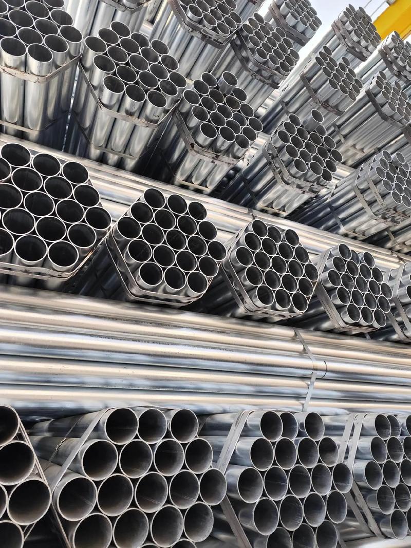
ERW BLACK Pipes. Electric Resistance Welded (ERW) Pipes are manufactured from Hot Rolled Coils / Slits. All the incoming coils are verified based on the test certificate received from steel mill for their chemistry and mechanical properties. ERW pipe is cold-formed into a cylindrical shape, not hot-formed.
Seamless pipe is manufactured by extruding the metal to the desired length; therefore ERW pipe have a welded joint in its cross-section, while seamless pipe does not have any joint in its cross-section through-out its length. In Seamless pipe, there are no welding or joints and is manufactured from solid round billets.

The 3 elements of pipe dimension Dimension Standards of carbon and stainless steel pipe (ASME B36.10M & B36.19M) Pipe Size Schedule (Schedule 40 & 80 steel pipe means) Means of Nominal Pipe Size (NPS) and Nominal Diameter (DN) Steel Pipe Dimension Chart (Size chart) Pipe Weight Class Schedule (WGT)
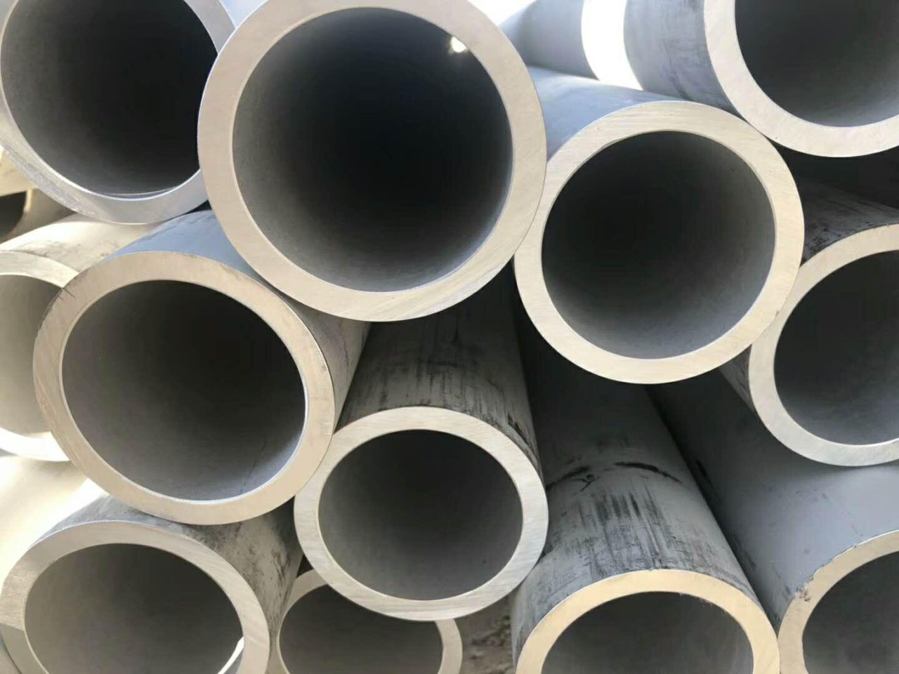
Seamless pipes are manufactured using a piercing process, where a solid billet is heated and pierced to form a hollow tube. Welded pipes, on the other hand, are formed by joining two edges of steel plates or coils using various welding techniques.
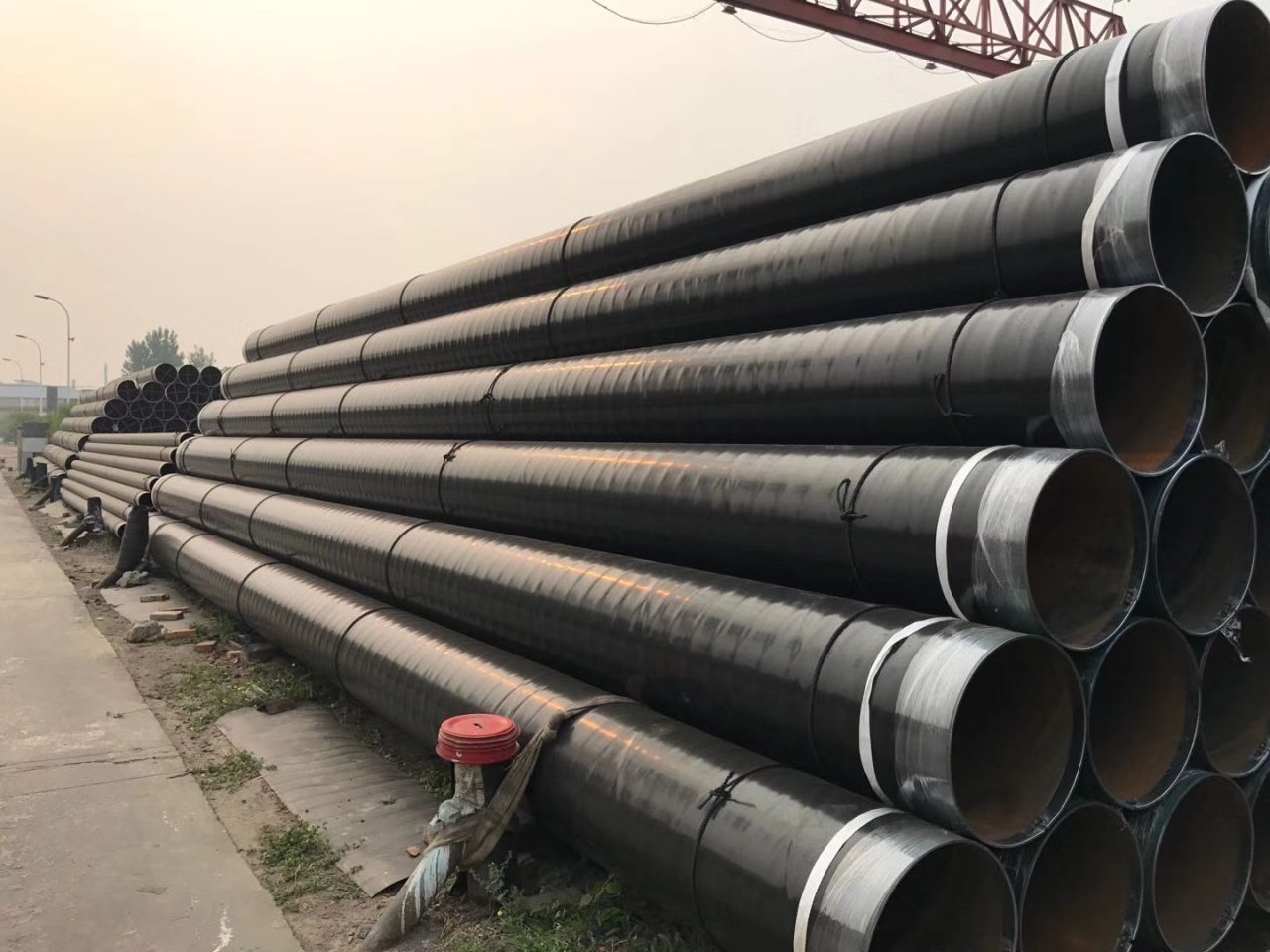
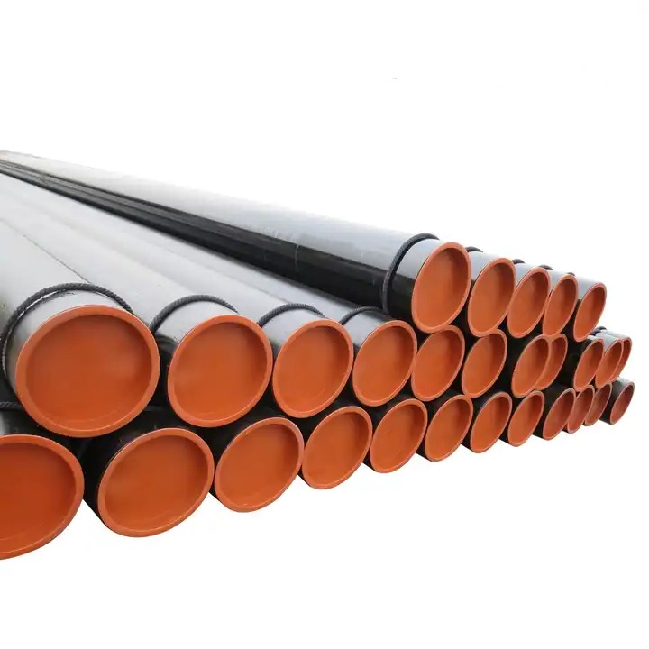
Carbon steel pipe is highly resistant to shock and vibration which making it ideal to transport water, oil & gas and other fluids under roadways. Dimensions Size: 1/8″ to 48″ / DN6 to DN1200 Thickness: Sch 20, STD, 40, XS, 80, 120, 160, XXS Type: Seamless or welded pipe Surface: Primer, Anti rust oil, FBE, 2PE, 3LPE Coated Material: ASTM A106B, A53, API 5L B, X42, X46, X52, X56, X60, X65, X70 Service: Cutting, Beveling, Threading, Grooving, Coating, Galvanizing
Type A- Used where ample head room is available. Specific elevation is desirable. Type B- Used where headroom is limited. Head attachment is a single lug. Type C- Used where headroom is limited. Head attachment is side by side lugs
Development History and Current Situation of Medium and High Frequency Heat-Expanded Seamless Steel Pipe Process
Technology, Application and Development Trend of Guanzhong Medium and High Frequency Heat-Expanded Seamless Steel Pipes
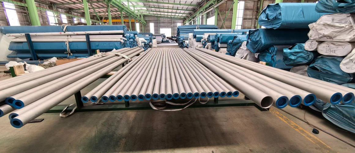
ASTM A276 TP304/304L Stainless Steel Welded Pipes: Standards, Properties, Manufacturing, Applications and Quality Control
The pursuit of integrity in maritime engineering often anchors itself to a single, critical component: the seamless steel pipe. To understand the trajectory of research and development in marine seamless pipes, one must look beyond the simple geometry of a hollow cylinder and see it as a metallurgical response to the unforgiving synergy of high pressure, thermal cycling, and chloride-induced corrosion.
The ASTM A53 ERW Galvanized pipe is a masterpiece of balanced engineering—efficient to produce, high in performance, and incredibly durable. By adhering to the most rigorous interpretations of the ASTM standard and surpassing international benchmarks like JIS and EN, our company delivers a product that is built to endure.
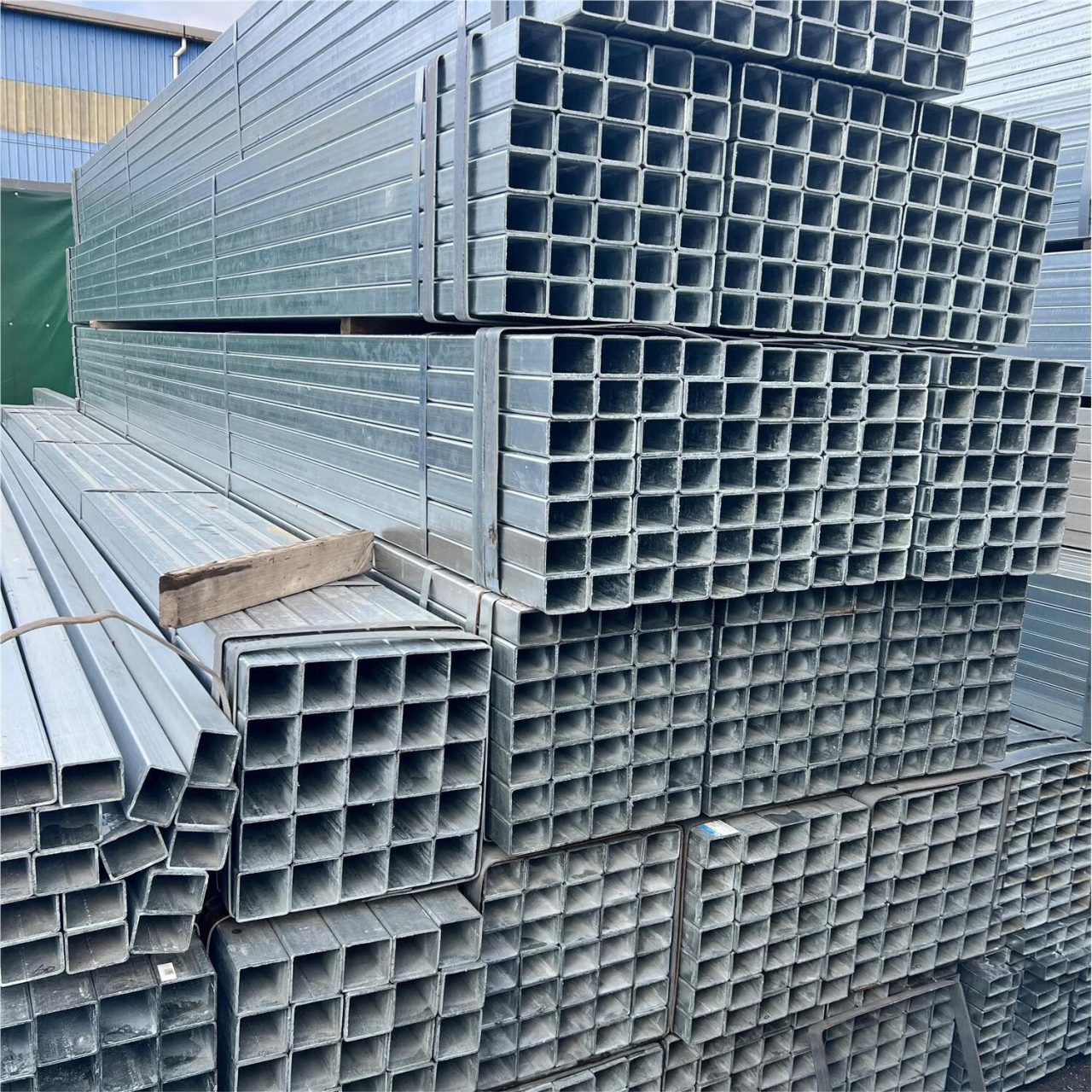
When you choose our galvanized Square Hollow Sections, you aren't just buying steel; you are investing in a structural foundation that is scientifically optimized for strength, chemically protected against the elements, and certified to the world’s most demanding standards.

However, 904L remains the indispensable choice for complex chemical environments where seawater is mixed with reducing acids, or for stagnant systems where its copper content may aid in resisting specific types of bio-corrosion. Furthermore, if the application requires extensive cold-forming or involves cryogenic conditions, the pure austenitic nature of 904L provides a level of reliability that the duplex structure cannot guarantee.
Ultimately, the 904L pipe is a testament to the power of precise alloying. It is a material that accepts the challenge of the most aggressive chemical environments, providing a service life that far exceeds standard stainless steels. By mastering the delicate balance of nickel, chromium, molybdenum, and copper, we provide a conduit that is as reliable as the physics upon which it is built.
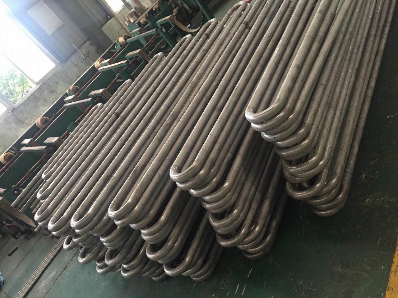
In advancing the technical narrative of our UNS N04400 ASTM B165 U-Bend tubes, we must pivot from the foundational metallurgy toward the sophisticated intersection of fluid dynamics and long-term structural reliability within the heat exchanger bundle.
In summary, the technical success of EN 10219 pipe relies on a deeply integrated relationship between the chemistry (controlled by $\text{CEV}$ for weldability and $\text{P}/\text{S}$ for toughness), the manufacturing process (cold forming for efficiency and work-hardening), and the final mechanical guarantees (yield strength and low-temperature impact energy). The progression from S235 to S355J2H is an engineering-driven pathway, providing a graded spectrum of performance that allows designers to precisely select the most efficient and safe material for any given structural task. The inherent structural efficiency of the hollow section form, combined with the excellent weldability and guaranteed toughness of these $\text{EN}$ grades, ensures their continued preeminence as the material of choice for the world's most vital structural works.
The API 5L Carbon Steel SSAW Pipe is a highly specialized piece of engineered infrastructure, a material solution fundamentally defined not by simple dimensional constraint or utility-grade corrosion protection, but by the relentless pursuit of high strength, reliable weld integrity, and exceptional fracture toughness, all necessary to ensure the safe, uninterrupted, and high-pressure conveyance of hydrocarbons, natural gas, or dense fluid slurries across vast geological and environmental landscapes. Unlike the familiar
The investment in API 5L Grade B Large Diameter SAW Steel Pipe is not merely a procurement decision; it is a strategic commitment to decades of predictable, high-volume fluid conveyance, underwritten by the most stringent certification system in the global pipeline industry
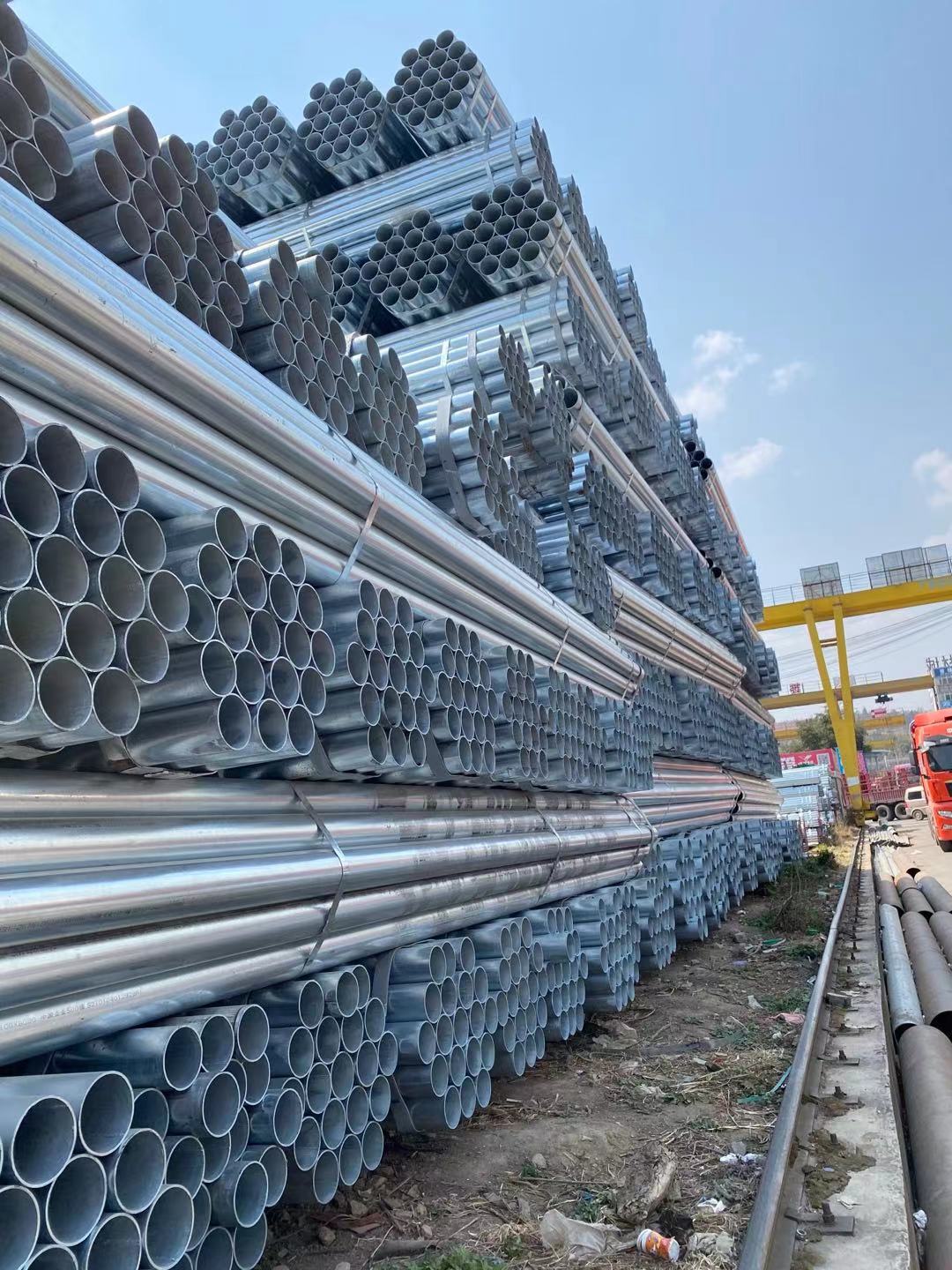
The Galvanized Steel Schedule 40 Pipe stands as an architectural pillar of conventional fluid transport, a design solution so ubiquitous in water pipeline infrastructure that its technical sophistication is often obscured by its sheer familiarity. Its continued dominance, even in the face of modern polymer and composite alternatives, is a testament to the optimized balance achieved between the raw, dependable strength of carbon steel and the elegant, self-sacrificial electrochemistry of the zinc coating
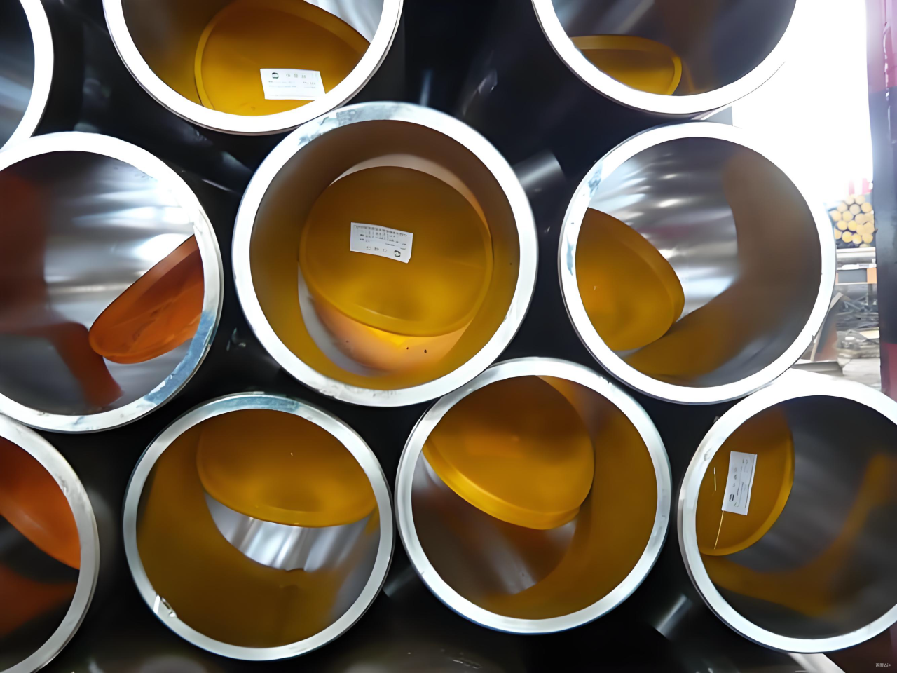
The pipe ends, which are left uncoated to facilitate field welding, require specific protection to maintain the cleanliness and integrity of the precisely machined bevels. The ends are protected with internal and external plastic or metal end caps to prevent physical damage, ingress of moisture, and internal contamination during storage and transit. For particularly long transit times, a temporary, easily removed corrosion inhibitor may be applied to the bare steel bevels to prevent surface rusting, ensuring the contractor receives a clean, ready-to-weld surface. This final logistical step closes the loop on Abtersteel’s commitment, ensuring that the high-integrity X60M PSL2 3PE LSAW pipe reaches the construction site in the same pristine, certified condition in which it left the factory.
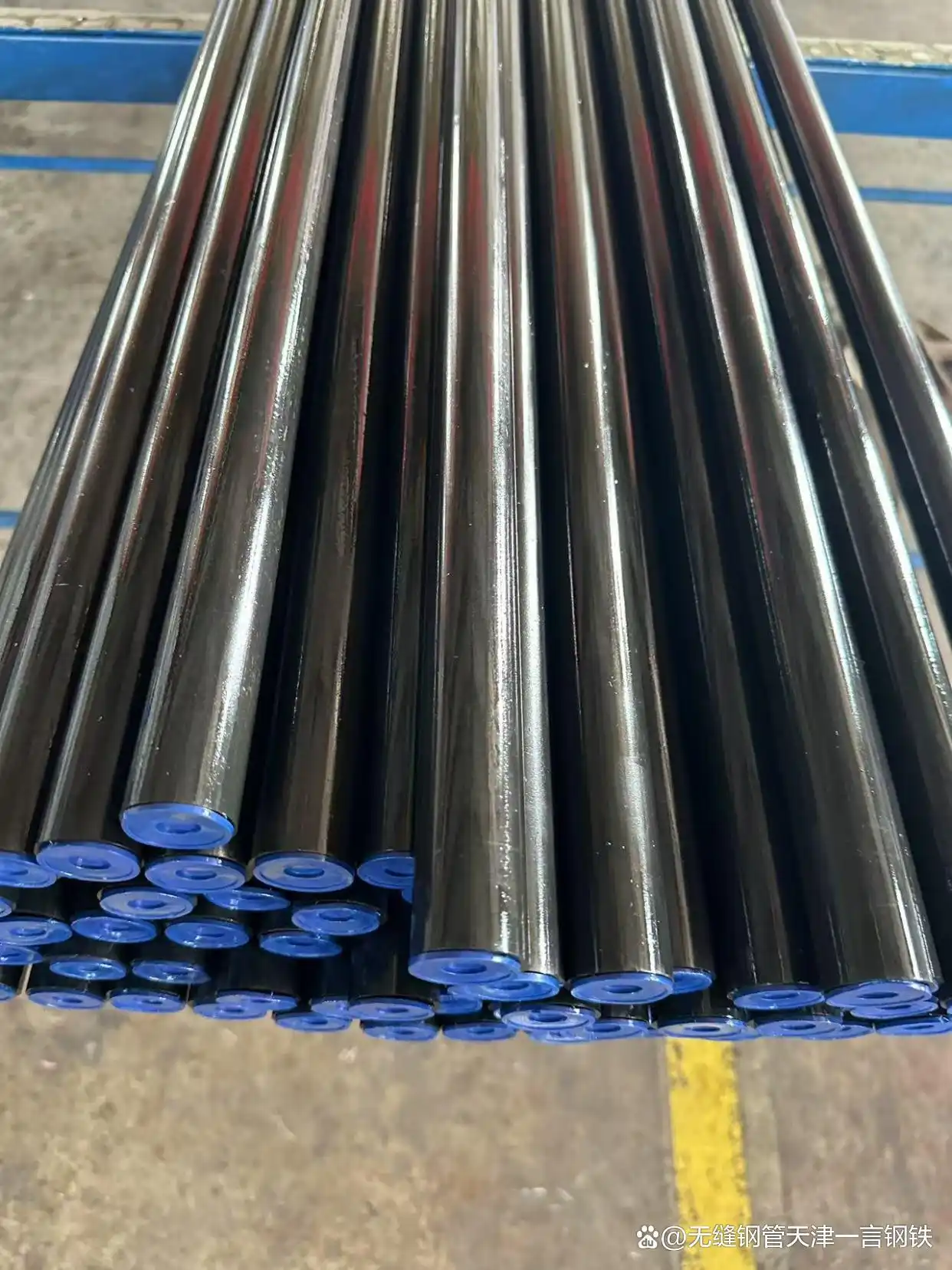
The DIN 2391 Grade St45 Seamless Pipe, supplied in the NBK condition, represents the pinnacle of precision steel tube engineering. Its excellence is a calculated outcome of advanced metallurgical control, severe cold-work plasticity, and meticulous thermal processing. Its functional superiority is validated by its proven ability to:
The DIN 2391 Grade St45 Seamless Pipe is, therefore, the product of choice where dimensional integrity is not a preference but a safety and performance prerequisite. Its use underpins the reliable operation of sensitive mechanical and fluid systems across every facet of modern industry, providing a foundational component that assures precision from the manufacturing stage all the way to decades of operational service.

ASTM A519 Seamless Steel Pipe in the venerable Chromium-Molybdenum (Cr-Mo) Alloy Grades—specifically 4130, 4140, 4142, 4145, and 4147

Honed Tubes for Hydraulic Cylinders and the associated Hydraulic Cylinder Steel Pipes
The endeavor to articulate a comprehensive, 3500-word exposition on the manufacture and engineering significance of ASTM A789/A789M Duplex Stainless Steel Pipes of Grades UNS S31803, S32205, and S32750 is not merely a task of compiling technical specifications
The API 5L Grade X65 steel pipe is the culmination of decades of metallurgical research, providing the foundational strength necessary for the modern energy grid. Yet, the true measure of its technical performance lies entirely within the choice between PSL1 and PSL2. The X65 PSL1 pipe offers a reliable, low-cost solution for standard applications, serving as the industry's basic assurance of quality.
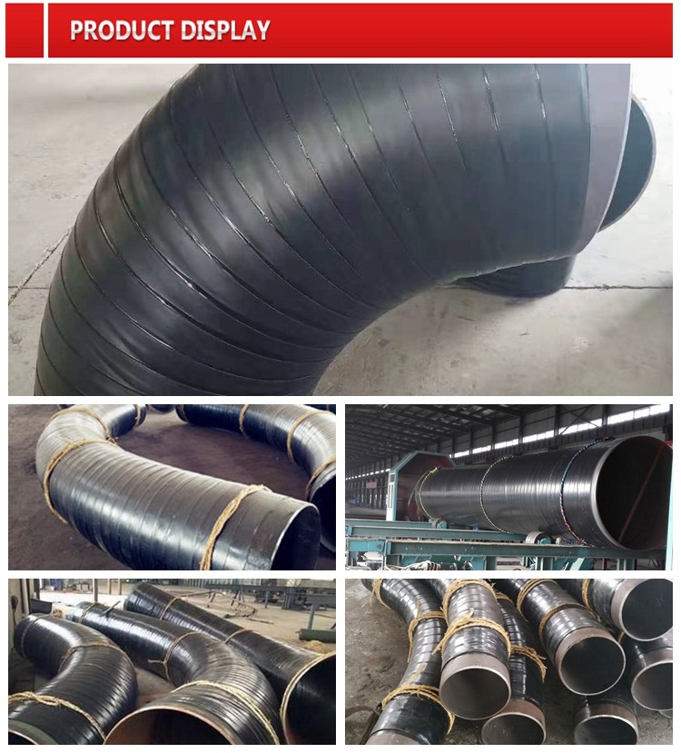
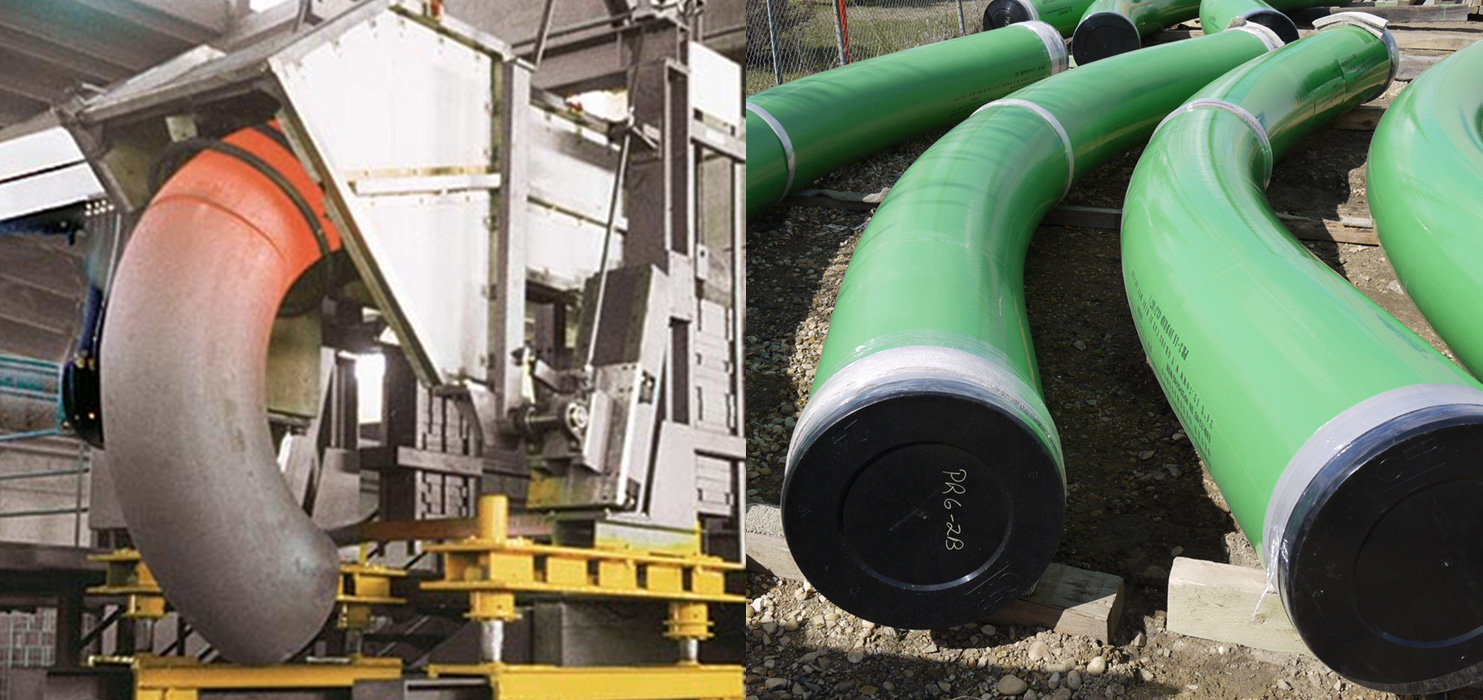
The modern transmission pipeline—the circulatory system of the global energy economy—is an intricate network defined by materials science and precision engineering. Within this network, the pipe bend is a critical, non-linear node where the constant force of high-pressure fluid flow meets the rigid necessity of directional change. Our product, the API 5L X52 and X60 Hot Induction Steel Pipe Bend, available in crucial and radii, is the embodiment of advanced thermal-mechanical processing applied to high-strength metallurgy. It is a highly engineered fitting designed to provide both structural integrity under extreme hoop stress and minimal hydraulic penalty, ensuring the long-term efficiency and safety of high-specification pipelines. Understanding this product requires a deep dive into the synergistic relationship between the chosen API 5L steel grade, the precise physics of hot induction bending, and the fundamental mechanical engineering principles governing pipeline flow.
The foundation of performance for these bends lies in the sophisticated chemistry and processing of the API 5L line pipe specification. The grades and are categorized as High-Strength Low-Alloy () steels, which are specially developed to handle the intense stresses inherent in transmitting natural gas, crude oil, or refined products over vast distances. The number following the ‘X’ denotes the minimum specified Yield Strength in thousands of pounds per square inch (), a fundamental parameter that directly dictates the maximum allowable operating pressure and, consequently, the required wall thickness of the pipe.
The scientific achievement in these steels is the ability to achieve high yield strength— () and () respectively—without incurring the metallurgical penalties typically associated with high-strength materials, such as poor weldability or reduced fracture toughness. This balance is maintained through meticulous micro-alloying. Trace additions of elements like Niobium (), Vanadium (), and Titanium (), often totaling less than of the composition, are the key. During the steel’s processing, these micro-alloy elements form minute precipitates () and restrict the growth of crystal grains, resulting in an exceptionally fine-grained microstructure. This grain refinement is the primary scientific mechanism that simultaneously elevates the yield strength and preserves the low-temperature Charpy V-notch toughness that is essential for resisting brittle fracture, particularly in frigid environments or under transient loading.
Furthermore, the Carbon Equivalent () of these steels is strictly controlled to remain at low levels. A low is a chemical necessity because it ensures the material’s excellent weldability, minimizing the risk of forming brittle martensitic structures in the Heat Affected Zone () during field welding operations. The choice between X52 and X60 is, therefore, a precise engineering decision—a calculated leverage of the material’s strength to optimize wall thickness based on the design hoop stress, guided by pipeline design codes like . The strength of the metal allows the designer to achieve the desired pressure capacity with the minimal amount of steel, translating directly into reduced material cost, lower shipping weight, and increased ease of installation, all while maintaining a controlled Yield-to-Tensile strength ratio ( ratio) to guarantee sufficient ductility and strain capacity before failure.
The creation of a precise pipe bend from high-strength steel cannot be achieved reliably through simple cold bending; the material would exhibit excessive springback, crack initiation, and uncontrolled geometric distortion. The necessary technology is Hot Induction Bending, a specialized thermo-mechanical process that relies on the precise application of electromagnetic energy and mechanical force.
The scientific core of this process is localized heating. The straight pipe is mounted in a bending machine, and a narrow induction coil encircles the bending zone. When high-frequency alternating current is passed through the coil, it generates a powerful alternating magnetic field. This field, according to Faraday’s law of induction, generates large eddy currents within the pipe wall, causing rapid and localized Joule heating. The bending zone is heated quickly and selectively to a precise temperature, typically between and —a range safely above the transformation temperature, making the material highly plastic and easy to form.
While the narrow band of the pipe is incandescent, a continuous mechanical force is applied, slowly pushing the pipe through the coil while a bending moment is exerted. This controlled, steady application of force causes the heated zone to deform plastically around a pivot point, forming the desired radius. This process is not just shaping; it is a rapid, localized heat treatment. The cooling rate immediately after the coil is crucial, often controlled by air or water sprays. This carefully managed thermal cycle is designed to prevent two simultaneous failure modes: first, grain coarsening at the high temperatures, which would lead to a catastrophic loss of toughness; and second, the formation of hard, brittle microstructures during rapid cooling. By controlling the cooling rate, the process aims to retain or even enhance the fine-grained structure established in the original parent material, ensuring that the finished bend maintains the specified or yield strength and the essential toughness.
The geometric challenge is managing the strain distribution. As the pipe bends, the material on the outer arc () is put into tension, leading to wall thickness thinning, while the inner arc () is compressed, causing wall thickness thickening. The thinning at the extrados is the most critical area, as it represents a local reduction in pressure containment capacity. The precision of the induction process, including the application of internal pressure or mandrels, is crucial for minimizing this thinning and ensuring the final wall thickness reduction remains within the strict limits (typically to ) mandated by pipeline codes and standards like ASME B31.8 and the specific induction bending standard, ASME B16.49. Any uncontrolled deviation here compromises the safety factor of the entire system.
The specification of and bends—where the radius () is five, eight, or ten times the nominal diameter (), respectively—is a direct reflection of optimizing a balance between hydraulic efficiency and mechanical stress.
From a Hydraulic Engineering perspective, the size of the bend radius directly impacts flow characteristics. Tighter bends () induce greater secondary flow (swirling or helical flow patterns) and higher localized turbulence. This turbulence results in a greater pressure drop across the bend and necessitates higher pumping energy to maintain flow rate. Conversely, larger radii ( and ) facilitate smoother, more laminar-like flow redirection. The bend is often selected for the largest diameter, highest flow rate pipelines because it minimizes energy dissipation and reduces internal erosion/corrosion risks associated with flow separation. The choice, therefore, directly influences the operational cost and efficiency of the entire pipeline over its life.
From a Mechanical Engineering standpoint, the radius dictates the severity of the stress concentration. A tighter bend results in a higher Stress Intensification Factor () and lower flexibility factor compared to a bend. The concentration of hoop stress, axial stress, and the bending moments at the extrados and the flanks of the bend demands greater local mechanical integrity. The use of high-yield material in a tight radius is often necessary to ensure the combined operational and bending stresses do not exceed the material’s yield point, even after accounting for the wall thickness reduction inherent to the forming process. The ASME B31 codes provide the mathematical framework for calculating the exact stress limitations based on these geometric ratios and the material properties, ensuring a quantified factor of safety for the entire range of product offerings.
The ability to produce these three distinct radii using the hot induction process—each requiring precise adjustments to the coil heating pattern, forming speed, and cooling rates—demonstrates the technical mastery required. For example, forming a bend requires a far longer, gentler thermal application than a bend, demanding a more extended zone of controlled heating to achieve the wider radius without introducing geometric anomalies like wrinkling or excessive ovality.
The ultimate proof of performance for an induction bend lies in its compliance with rigorous quality control protocols and standards, chief among which is the final Hydrostatic Test. Every finished bend is subjected to internal pressure significantly higher than its maximum intended operating pressure (), stressing the metal beyond its nominal yield point. This is the definitive final step, providing proof that the material is free from critical defects and that the wall thickness integrity, even at the thinnest extrados, is sufficient to contain the design pressure.
Beyond the hydrostatic test, comprehensive Non-Destructive Evaluation () is mandatory. Ultrasonic Testing () is used to map the wall thickness profile across the entire bend, verifying that the thinning at the extrados remains within the code limits. Magnetic Particle Inspection () or Liquid Penetrant Inspection () is performed on the internal and external surfaces to search for microscopic surface-breaking flaws or cracks that could have initiated during the severe thermal and mechanical cycling of the induction process.
The final product, therefore, is an integrated component where the high-strength metallurgy of API 5L X52/X60 is perfectly matched to the controlled thermal physics of Hot Induction Bending. The resulting fittings, with their verified 5D, 8D, or 10D geometry, ensure that the pipeline can be constructed with confidence, maximizing flow capacity and minimizing maintenance requirements while adhering to the most stringent safety and engineering standards governing energy transportation infrastructure worldwide.
abtersteel is a China based line pipe manufacturer and supplier. Our main products include boiler steel tube, corrosion protection steel pipe, insulated pipeline, to name a few. All of our high quality products are offered at competitive prices. The full chain of manufacturing abrasion resistant steel pipe, SSAW steel pipe, etc. can be completed in China, even in one city. Lower manufacturing cost saves your purchasing cost. The detailed information of each product is shown in the corresponding product page.
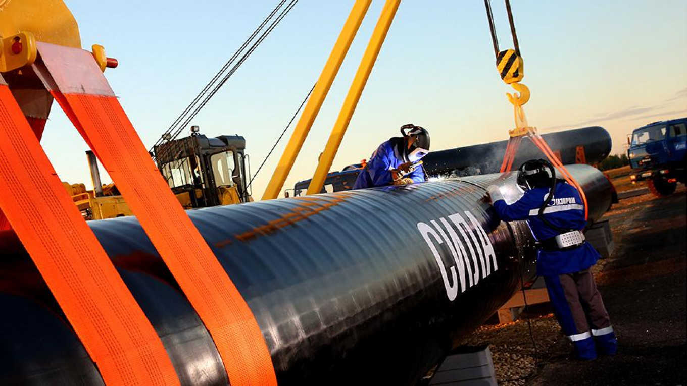
Pipe fittings are used in plumbing systems to connect straight sections of pipe or tubes, to accommodate different sizes or shapes, and for other purposes such as regulating (or measuring) fluid flow. These fittings are used in plumbing systems to control the transfer of water, gas or liquid waste within pipes or plumbing systems in domestic or commercial environments. Fittings (especially uncommon types) require money, time, materials and tools to install and are an important part of plumbing and plumbing systems. Common pipe fittings mainly include: flange, elbows, couplings, unions, spools, reducers, bushings, tees, diverter tees, crosses, caps, plugs, barbs and valves. Although valves are technically fittings, they are usually discussed separately.
Pipe fitting bodies are usually made of the same base material as the pipe or tubing they are connected to: copper, steel, PVC, CPVC or ABS. Any material permitted by plumbing, health or building codes (as applicable) may be used, but it must be compatible with the other materials in the system, the fluid being conveyed, and the temperature and pressure inside (and outside) the system. Brass or bronze fittings over copper Common in plumbing and plumbing systems. Fire resistance, shock resistance, mechanical strength, anti-theft and other factors also affect the choice of material for pipe fittings.
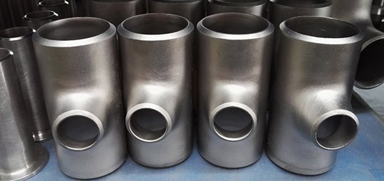
Material Stainless Steel ASME / ASTM SA / A403 SA / A 774 WP-S, WP-W, WP-WX, 304, 304L, 316, 316L, 304/304L, 316/316L, DIN 1.4301, DIN1.4306, DIN 1.4401, DIN 1.4404 Dimension ANSI B16.9, ANSI B16.28, MSS-SP-43 Type A, MSS-SP-43 Type B, JIS B2312, JIS B2313 Thickness Schedule 5S, 10S, 20S, S10, S20, S30, STD, 40S, S40, S60, XS, 80S, S80, S100, S120, S140, S160, XXS and etc.
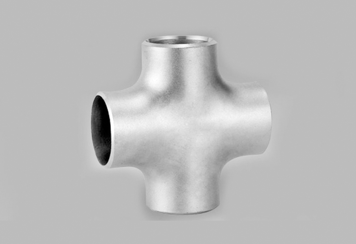
Cross fittings allow for the branching of pipes, enabling the distribution of water or other fluids to various fixtures or areas. They are commonly used in water supply systems, irrigation systems, and heating systems.
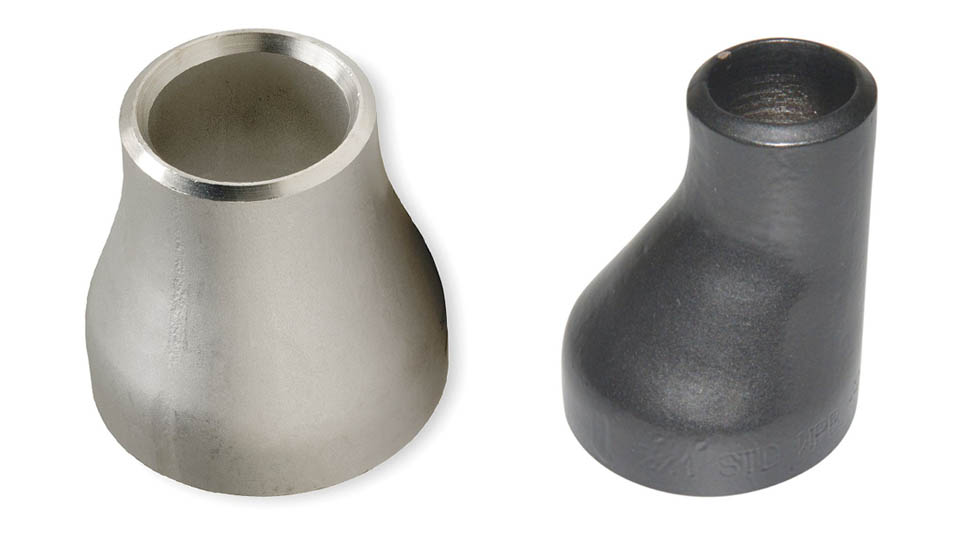
Concentric reducers are used where the pipework is vertically installed and at the discharge side of pumps. Eccentric reducers are more often used when the pipework lays on a pipe rack. Because of the flat side, aligning and securely mounting the pipes to the rack is easier.
In the vast, interconnected world of industrial power generation and thermal processing, the boiler stands as the single most critical component, a high-pressure furnace where the raw power of heat is converted into usable energy. The integrity of this entire operation rests upon the unseen performance of thousands of feet of **boiler tubes**. These are not mere conduits for water or steam; they are sophisticated heat transfer devices that must simultaneously withstand immense internal pressures, aggressive external heat flux, severe thermal cycling, and the relentless, slow-motion threat of **creep deformation**. To ensure safety, reliability, and global interchangeability in this high-stakes environment, the **Japanese Industrial Standard (JIS) G3461** provides a highly specialized and rigorous set of specifications for **Carbon Steel Boiler and Heat Exchanger Tubes**. This standard is a technical covenant, dictating precise material science, manufacturing fidelity, and a mandatory gauntlet of testing.
The journey into JIS G3461 is a deep dive into the engineering compromises necessary for survival in extreme conditions. While other standards, such as JIS G3454, deal with pressure piping, G3461 operates on a different level of scrutiny. Its focus is explicitly on materials that perform the function of *heat exchange*, meaning the tube wall must manage a sharp thermal gradient. This critical function dictates the stringent requirements found within the standard’s grades—**STB 340, STB 410, and STB 510**—each a variation on a theme, optimized for distinct zones within the boiler, from the moderate heat of the economizer to the intense, pressure-laden environment of the evaporator and superheater sections. Understanding the requirements of G3461 means understanding the very backbone of modern thermal power.
The **JIS G3461** designation, with the **STB** (Steel Tube Boiler) identifier, specifies the necessary criteria for steel tubes used in transferring heat at elevated temperatures, typically up to a practical limit of around $450^\circ\text{C}$ to $500^\circ\text{C}$ for carbon steel, depending heavily on the internal pressure and the specific design code being applied (such as ASME). Above this threshold, metallurgical factors like **graphitization** (the precipitation of carbon that leads to brittle fracture) and accelerated creep necessitate the use of low-alloy chromium-molybdenum (Cr-Mo) steels, which are governed by the related standard, JIS G3462.
The three core grades within G3461 are defined by their minimum guaranteed ultimate tensile strength in megapascals ($\text{MPa}$):
The standard ensures not only strength but also dimensional uniformity and material consistency, which is paramount when hundreds or thousands of identical tubes must be seamlessly fitted, expanded, or welded into header drums and tube sheets. Without the rigid adherence to these specifications, the complex flow dynamics and thermal distribution within a boiler would be rendered unpredictable, potentially leading to catastrophic failure.
| Parameter | Specification | Grades Covered |
|---|---|---|
| Standard Name | Carbon Steel Boiler and Heat Exchanger Tubes | STB 340, STB 410, STB 510 |
| Designator | JIS G3461 (STB) | |
| Primary Function | Heat transfer and pressure containment up to $\approx 500^\circ\text{C}$ | |
| Typical Application | Economizers, Water-Wall Tubes, Evaporators, Low-Pressure Superheaters | STB 340 (Lower P/T), STB 410 (General P/T), STB 510 (High P/T) |
The manufacturing method is the foundation of the tube’s integrity and is categorized into two processes under JIS G3461: **Seamless (S)** and **Electric Resistance Welded (ERW) (E)**. The choice between these two is driven by the operating conditions, particularly the risk associated with the failure of a weld seam under stress.
Seamless tubes are produced from a solid, cylindrical billet that is heated and pierced to create a hollow shell, which is then rolled and often cold-drawn to achieve the final size and wall thickness. The absence of any fusion or join ensures a continuous, uniform metallic structure free of the metallurgical discontinuities inherent in a weld. This is critical for tubes exposed to the highest internal pressures and **cyclic thermal loading**, such as in steam drums or furnace water walls, where a defect could quickly propagate into a failure. The seamless process allows the final product to have superior resistance to **creep rupture**, as the stress is distributed evenly across the entire circumference. Seamless tubes produced to G3461 specifications undergo mandatory final heat treatments—typically **normalization** for hot-finished tubes or **annealing** for cold-finished tubes—to relieve internal stresses and restore the optimal microstructure for long-term high-temperature service.
ERW tubes are manufactured from continuous steel strip (skelp), which is cold-formed into a tube shape. The edges are joined by high-frequency electric current and pressure, fusing them without the addition of filler metal. Modern ERW processes are highly controlled and can achieve exceptional dimensional precision, particularly in wall thickness. This precision is sometimes favored in non-critical heat exchangers like economizers where the priority is thin, uniform walls for maximum heat transfer. However, because a weld seam is present, the standard demands rigorous verification. This includes mandatory post-weld **normalization** of the weld zone to ensure the grain structure in that area is equivalent to the base metal, followed by intensive non-destructive testing to guarantee the weld is free from flaws or lack of fusion.
| Type | Designator | Process | Mandatory Heat Treatment |
|---|---|---|---|
| Seamless | S | Hot piercing, rolling, (optional cold drawing) | Normalization (Hot-finished) or Annealing (Cold-finished) |
| ERW | E | Cold forming, High-frequency welding | Normalization/Stress Relief of the weld seam and adjacent HAZ |
*Note: Heat treatment is critical to achieve the specified mechanical properties, relieve residual stress, and ensure microstructural stability for high-temperature creep performance.
The chemical recipe for JIS G3461 steel is not arbitrary; it is an optimized formula designed to maximize desirable properties while minimizing detrimental ones. The composition must ensure the necessary strength at elevated temperatures, prevent failure from high-temperature mechanisms, and maintain excellent **weldability**—an essential feature for tube-to-tube sheet connections.
The primary elements are controlled to create the differences between the grades. The carbon content ($\text{C}$) is the single most important factor determining the strength, increasing slightly from STB 340 to STB 510 to achieve the higher tensile properties. However, this comes with a trade-off: higher carbon content complicates field welding, increasing the risk of brittle microstructures in the heat-affected zone (HAZ) unless strict pre- and post-weld heat treatments are followed.
The essential roles of **Manganese ($\text{Mn}$) and Silicon ($\text{Si}$)** involve deoxidation during steelmaking, refining the grain structure, and boosting strength. Manganese is also crucial for counteracting the effects of sulfur, improving the steel’s hot ductility. Conversely, the concentration of impurities—**Phosphorus ($\text{P}$) and Sulfur ($\text{S}$)**—is strictly capped at a low maximum ($\le 0.035\%$). This constraint is non-negotiable for boiler tubes, as these elements readily segregate to grain boundaries, dramatically reducing toughness and accelerating high-temperature embrittlement, thereby undermining the tube’s resistance to creep and thermal stress. The low limits ensure material cleanliness and predictable performance over the tube’s multi-decade design life.
| Grade | $\text{C}$ (Max) | $\text{Si}$ (Max) | $\text{Mn}$ | $\text{P}$ (Max) | $\text{S}$ (Max) |
|---|---|---|---|---|---|
| STB 340 | $0.20$ | $0.35$ | $0.30 – 0.90$ | $0.035$ | $0.035$ |
| STB 410 | $0.25$ | $0.35$ | $0.30 – 1.00$ | $0.035$ | $0.035$ |
| STB 510 | $0.30$ | $0.35$ | $0.30 – 1.00$ | $0.035$ | $0.035$ |
*Note: The minimum manganese content is crucial for toughness; the stringent maximum limits on P and S are essential for high-temperature service integrity.
The mechanical properties define the material’s resistance to pressure and deformation. The specified minimums for **Tensile Strength ($\sigma_{ts}$)**, **Yield Point/Strength ($\sigma_{y}$)**, and **Elongation** are the core criteria that determine a tube’s selection for a specific location within the boiler system.
The **Yield Strength** is the most critical number for design engineers, as it sets the maximum permissible stress. By design code mandates, the operating pressure stress must be kept at a fraction of the yield strength to ensure the tube remains in the elastic range for its entire lifespan. For a given internal pressure, the superior yield strength of **STB 410** over STB 340, or **STB 510** over STB 410, allows the design engineer to specify a **thinner wall thickness**. This saves material, reduces weight, and significantly improves the tube’s most important function: the transmission of heat from the fire side to the water side. A thinner wall means less resistance to heat flow, increasing the boiler’s thermal efficiency.
**Elongation**, a measure of the material’s **ductility**, is equally vital. It provides the assurance that the tube will not fail in a brittle manner under impact or during the intense forming processes required during boiler fabrication, such as flaring or expanding the tube ends to create a leak-proof mechanical joint with the tube sheet. As expected, the higher strength grades (STB 410 and STB 510) exhibit slightly lower minimum ductility than the STB 340, reflecting the inherent trade-off between strength and flexibility in carbon steel metallurgy.
| Grade | Tensile Strength (Min.) $\text{N/mm}^2 (\text{MPa})$ | Yield Point/Strength (Min.) $\text{N/mm}^2 (\text{MPa})$ | Elongation (Min.) (Varies by Test Piece) |
|---|---|---|---|
| STB 340 | 340 | 175 | $25\%$ |
| STB 410 | 410 | 215 | $22\%$ |
| STB 510 | 510 | 285 | $18\%$ |
*Note: The elongation value is highly dependent on the thickness and the specific test specimen (No. 4, No. 5, No. 11, No. 12) used in accordance with the standard.
The adherence to precise dimensional tolerances in JIS G3461 is not simply a matter of aesthetics or ease of assembly; it is intrinsically linked to **creep life** and **thermal efficiency**. The standard mandates extremely tight controls on both the outside diameter (OD) and the wall thickness (WT).
For a boiler tube, the **Wall Thickness** tolerance is the most crucial geometric parameter. Because stress is inversely proportional to thickness, any section of the tube that is thinner than specified will experience higher localized stress, accelerating the slow process of creep deformation. If the negative tolerance is too large (i.e., the tube is too thin), the design life can be severely compromised, leading to premature failure and dangerous hot spots. Therefore, G3461 specifies tight limits, often restricting the negative tolerance to be much smaller than the positive tolerance—sometimes as little as $\pm 10\%$ of the nominal WT, or even a strictly positive tolerance (e.g., $+15\%$ to $-0\%$) for high-risk, high-pressure tubes, guaranteeing the minimum thickness is always present.
The **Outside Diameter (OD)** tolerance is critical for fit-up. Tubes must be precisely sized to fit into the drilled holes of the header drums and tube sheets. A tolerance that is too loose prevents the formation of a secure, leak-tight **expanded joint**. The OD tolerance is often specified as a fixed absolute value for smaller diameters, ensuring high precision. **Straightness** and **ovality** (out-of-roundness) are also strictly controlled to ensure the tubes can be properly coiled, bent, and inserted into complex heat exchanger bundles using automated machinery without binding.
| Dimension/Process | Outside Diameter (OD) Tolerance | Wall Thickness (WT) Tolerance (Typical) |
|---|---|---|
| Seamless (Hot-finished) | $\pm 1\%$ of OD, or $\pm 0.5 \text{ mm}$ (Smaller Sizes) | $+15\%$ / $-12.5\%$ |
| Seamless (Cold-finished) / ERW | $\pm 0.3 \text{ mm}$ to $\pm 0.5 \text{ mm}$ (Tighter Control) | $\pm 10\%$ |
| Straightness | Maximum deviation | $1 \text{ mm}$ per $1000 \text{ mm}$ length |
*Note: The negative wall thickness tolerance is the single most scrutinised dimensional check under this standard to guarantee design life and pressure capacity.
The extreme service conditions faced by JIS G3461 tubes dictate a comprehensive and mandatory inspection and testing protocol. These tests are the final, non-negotiable proof that the tube meets all specifications and is fit for service. The protocol is divided into mechanical tests (verifying material properties) and non-destructive tests (verifying structural integrity).
The core of the mechanical verification process involves subjecting samples to severe deformation:
These tests are designed to catch flaws invisible to the eye that could lead to catastrophic failure:
| Test Type | JIS G3461 Requirement | Primary Function |
|---|---|---|
| Chemical Analysis | Ladle and Product Analysis | Confirm C, Mn, P, S content for creep and weldability. |
| Hydrostatic Test | Every tube length | Verify pressure containment and leak-tightness. |
| Flaring Test | Sample testing | Confirm ductility for tube-to-tube sheet expansion. |
| Flattening Test | Sample testing | Verify ductility and structural soundness, especially at welds. |
| NDE (UT or ET) | Every tube length (Weld Zone for ERW) | Detect internal/surface flaws invisible to the eye. |
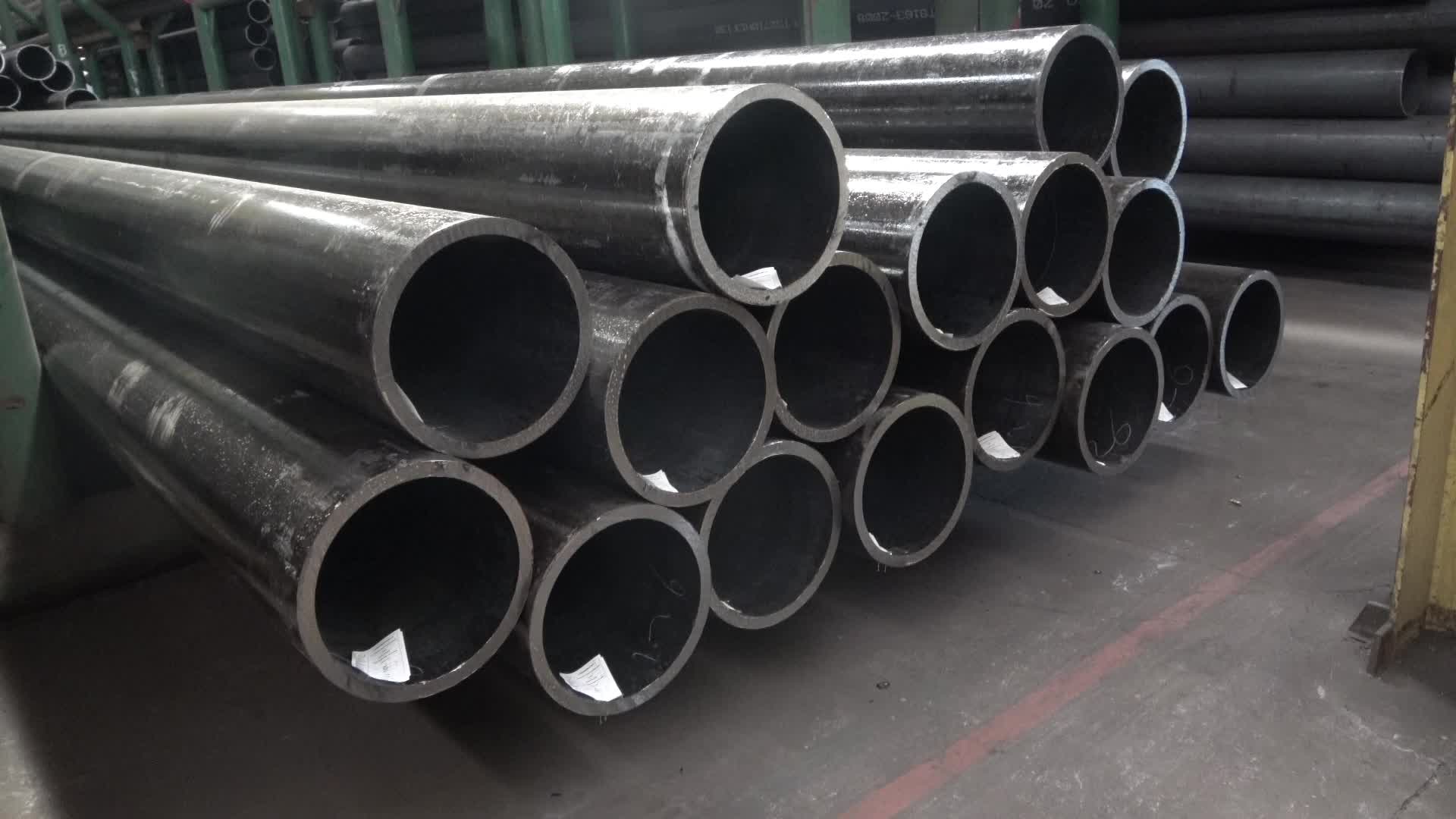
Boiler Pipe Application: 1 General boiler pipes are mainly used to manufacture water-cooled wall pipes, boiling water pipes, superheated steam pipes, superheated steam pipes for locomotive boilers, large and small smoke pipes and arch brick pipes. 2 high pressure boiler tubes are mainly used to manufacture superheater tubes, reheater tubes, air ducts, main steam tubes, etc. for high pressure and ultra high pressure boilers.
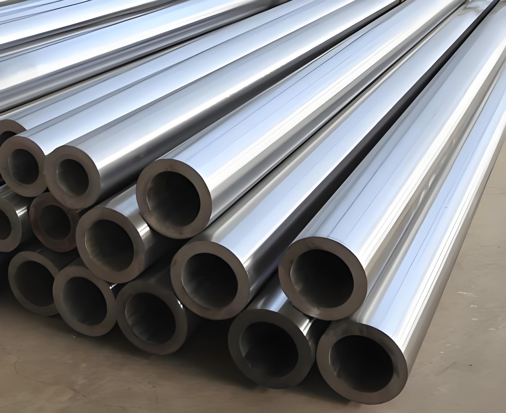
Boiler Steel Pipes are critical components in many industrial applications, providing reliable performance under extreme conditions. By adhering to strict quality standards and understanding the key properties and classifications of these tubes, industries can ensure the safe and efficient operation of their thermal systems.
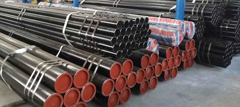
ASTM A210 Grade A1 Seamless Tube shall be made by the seamless or welding process with the addition of no filler metal in the welding operation. The offered ASTM A210 GR A1 CS Seamless Tubes is availed in diverse sizes and other related specifications, to meet requirements of our prominent clients.ASME SA 210 Gr.A1 Boiler Pipes that is designed according to set industry standards. As per the needs and requirements of our clients, we are involved in providing ASME SA 210 Gr. A1 Boiler Tubes. Buy ASTM A210 Grade A1 Boiler Tubes at reasonable cost from us.
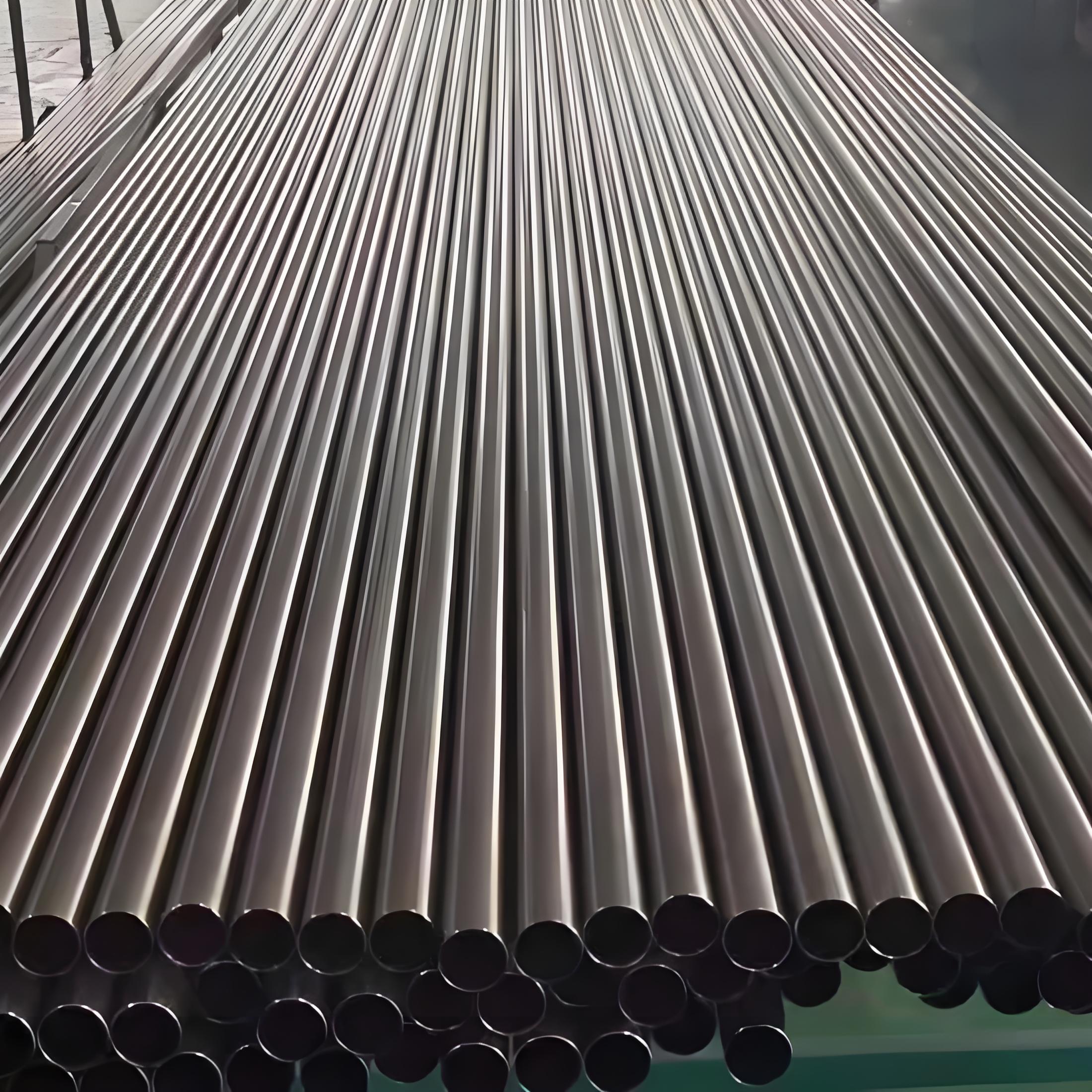
ASTM B861 titanium alloy seamless pipes are a premium choice for boiler applications, offering unmatched corrosion resistance, high-temperature strength, and lightweight properties. Compliant with ASTM B861 and ASME SB861, these pipes in grades like 2, 7, and 12 meet the demands of power generation, chemical processing, and marine boiler systems. Despite higher costs, their durability and performance justify their use in critical applications. For technical data or quotes, contact suppliers like abtersteel.com
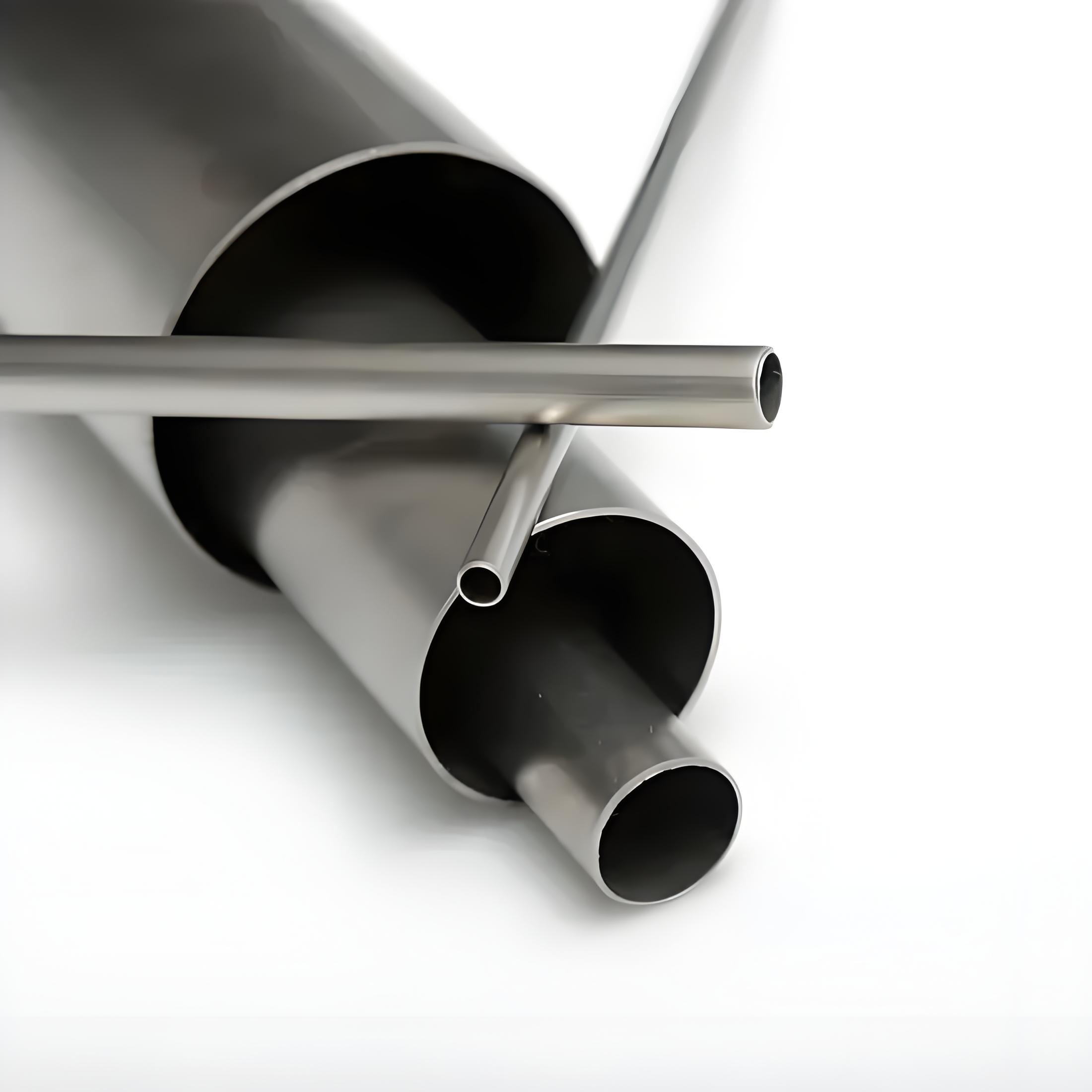
ASME SB338 Grade 7 titanium heat exchanger tubes, alloyed with palladium, offer unmatched corrosion resistance, thermal efficiency, and lightweight properties for demanding applications. Compliant with ASME SB338 and ASTM B338, these tubes excel in chemical processing, power generation, desalination, and marine heat exchangers. Their durability, enhanced by palladium, justifies their use despite higher costs. For technical data or quotes, contact suppliers like abtersteel.com
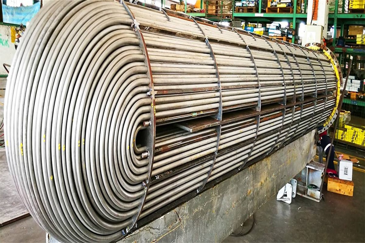
Coda: TP321 tubes, alloyed aegis of the blaze, orchestrate superheat—compositions cohesive, dimensions deft, strengths steadfast—eternal emissaries of energy's ember.
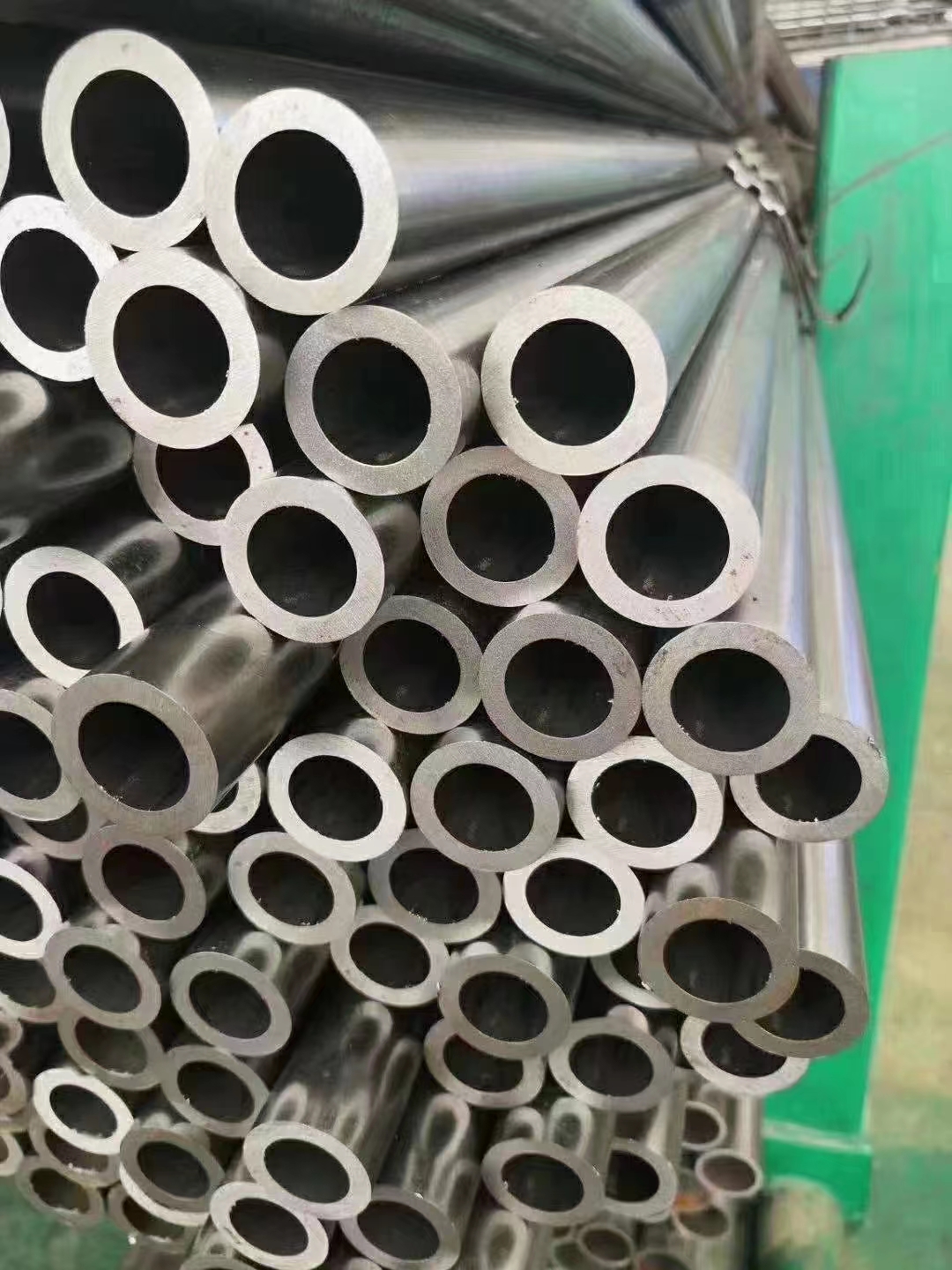
The efficiency and safety of modern thermal engineering—encompassing power generation, petrochemical processing, and heavy industrial heating—rely fundamentally on the integrity of their pressure-containing components. Among the most critical of these are the pipes used to convey hot fluids and steam. In the global landscape of material standards, the Japanese Industrial Standard (JIS) G3454 sets a rigorous benchmark for Carbon Steel Pipes for Pressure Service, with the STPG designation being a globally recognized material for boiler and heat exchanger applications. This standard is not merely a set of specifications; it is a meticulously defined framework that ensures the reliability, durability, and safety of piping systems operating under the unforgiving conditions of high temperature and high pressure. To truly appreciate the role of STPG pipes, one must delve into the specifics of its composition, mechanical properties, manufacturing precision, and the demanding applications it serves.
The designation JIS G3454 falls under the broader category of Japanese Industrial Standards (JIS) related to ferrous materials. Specifically, G3454 is the standard dedicated to Carbon Steel Pipes for Pressure Service. The “STPG” nomenclature within this standard is an acronym derived from the Japanese terms for Steel (S), Tube (T), Pressure (P), and General (G), indicating a general-purpose steel pipe intended for pressure applications. This is distinct from other JIS standards like G3455 (High Pressure Service) or G3461 (Boiler and Heat Exchanger Tubes), though there are often overlaps in application.
The primary function of pipes manufactured to JIS G3454 STPG specifications is the safe and efficient conveyance of pressurized fluids, gases, and steam at elevated temperatures. Their application typically involves components such as steam lines, headers, economizers, and various piping within boiler plants where the operating temperature does not typically exceed $350^\circ\text{C}$ to $400^\circ\text{C}$. Beyond these temperatures, creep phenomena become significant, often necessitating the use of low-alloy steels (like Cr-Mo steels defined by JIS G3458 or international equivalents). Therefore, the STPG grades are the workhorses of the conventional pressure piping systems that form the heart of countless industrial operations. The two primary grades within this standard, STPG 370 and STPG 410, are differentiated by their specified minimum tensile strength, which is the cornerstone of their selection criteria.
The strict adherence to this standard by Japanese and international manufacturers alike provides a crucial assurance of quality. It establishes uniform criteria for material composition, dimensions, tolerances, testing procedures, and documentation. This global interchangeability and predictability are vital in large-scale engineering projects where materials from various suppliers must integrate seamlessly into a single, cohesive, high-integrity system.
The foundational performance of any steel material is dictated by its precise chemical composition. For STPG pipes, the composition is carefully controlled to balance two critical, often conflicting, requirements: high tensile strength to withstand internal pressure and excellent weldability for ease of fabrication and installation in complex piping networks. As carbon steel, the primary alloying elements are carbon, silicon, manganese, phosphorus, and sulfur.
The grades STPG 370 and STPG 410 are fundamentally low-carbon steels, with carbon content being the key determinant of their strength differential. A lower carbon content in STPG 370 enhances its ductility and weldability, making it suitable for applications where extensive forming or complex welding is necessary. Conversely, the slightly higher carbon and manganese content in STPG 410 contribute to its increased tensile and yield strength, allowing it to handle higher operating pressures, albeit with a marginal reduction in ease of welding. The limits on residual elements like phosphorus ($\text{P}$) and sulfur ($\text{S}$) are extremely stringent, as these impurities can lead to issues such as hot shortness during rolling and reduced toughness, which are unacceptable risks in pressure service piping.
The following table details the maximum permissible chemical composition for the two primary grades, reflecting the stringent control necessary for pressure piping integrity (all values are in mass percent, maximum unless otherwise noted):
| Element | STPG 370 | STPG 410 | Purpose/Impact |
|---|---|---|---|
| Carbon (C) | $\le 0.25$ | $\le 0.30$ | Primary strength-imparting element; higher C reduces weldability. |
| Silicon (Si) | $\le 0.35$ | $\le 0.35$ | Deoxidizer; increases strength and hardness slightly. |
| Manganese (Mn) | $0.30 – 0.90$ | $0.30 – 1.00$ | Increases strength, hardness, and wear resistance; counteracts P and S effects. |
| Phosphorus (P) | $\le 0.040$ | $\le 0.040$ | Highly restricted impurity; reduces ductility and toughness (cold shortness). |
| Sulfur (S) | $\le 0.040$ | $\le 0.040$ | Highly restricted impurity; promotes hot shortness and lowers impact strength. |
*Note: The actual specifications may include specific carbon equivalent (CE) limits or more detailed alloying restrictions, which are crucial for welding procedure specification (WPS). The maximum P and S content is often tighter in practice, but the standard specifies $\le 0.040\%$.
The selection of a pipe for pressure service is ultimately governed by its ability to resist the stress exerted by the internal pressure and external loads. The mechanical properties—specifically **tensile strength**, **yield strength**, and **elongation**—are the quantitative measures of this resistance. The numerical designation in the STPG name is directly tied to the minimum specified tensile strength in megapascals ($\text{MPa}$).
STPG 370 denotes a pipe material with a minimum tensile strength of $370 \text{ MPa}$, while STPG 410 specifies a minimum tensile strength of $410 \text{ MPa}$. The yield strength, which is the point at which the material begins to deform permanently, is equally critical for design calculations to ensure the pipe operates safely within its elastic limit. Elongation, a measure of the material’s ductility, ensures the pipe can withstand a degree of deformation without brittle fracture—a non-negotiable requirement for pressurized components.
The following table outlines the minimum mechanical requirements specified by JIS G3454:
| Property | Unit | STPG 370 (Min.) | STPG 410 (Min.) |
|---|---|---|---|
| Tensile Strength ($\sigma_{ts}$) | $\text{N/mm}^2$ ($\text{MPa}$) | 370 (or 373) | 410 (or 412) |
| Yield Strength ($\sigma_{y}$) | $\text{N/mm}^2$ ($\text{MPa}$) | 215 (or 216) | 245 |
| Elongation (Longitudinal, No. 4/5 Test Piece) | $\%$ | $28 \text{ min.}$ | $24 \text{ min.}$ |
*Note: The minimum elongation requirement varies significantly based on the sample type (No. 4, No. 5, No. 11, No. 12) and whether the test is conducted longitudinally or transversely to the pipe axis. The values above represent common minimums for design reference. N/mm$^2$ and MPa are interchangeable units for stress.
The design engineer relies heavily on the guaranteed minimum yield strength, as it forms the basis for wall thickness calculations according to codes like ASME B31.1 or B31.3. A higher yield strength, as offered by **STPG 410**, allows for a potentially thinner wall for the same design pressure, leading to material savings, reduced weight, and improved heat transfer efficiency—a significant factor in heat exchanger and boiler design.
The microstructure and resulting mechanical performance of an STPG pipe are intrinsically linked to its manufacturing method. JIS G3454 covers both **Seamless** and **Electric Resistance Welded (ERW)** pipe processes, although for critical high-pressure and high-temperature boiler applications, **seamless** pipe is overwhelmingly preferred due to its superior integrity and uniformity.
Seamless STPG pipes are produced by piercing a hot, solid billet of steel, which is then rolled and drawn to the final specified dimensions. The absence of a weld seam means there are no inherent metallurgical or structural discontinuities in the pipe body. This makes seamless pipe the ideal choice for applications where the pipe will be subjected to the highest internal pressures, thermal cycling, and complex bending or coiling during fabrication. The uniform grain structure and absence of a potential weld defect path provide the highest level of assurance against catastrophic failure, which is paramount in a boiler environment.
ERW STPG pipes are manufactured from a flat strip (skelp) that is cold-formed into a cylinder and then welded along the longitudinal seam by applying an electric current that melts the edges. While modern ERW processes have achieved remarkable quality, the presence of the weld seam can sometimes introduce potential weak points. For very demanding pressure service applications, the designer may be restricted by code to use seamless pipes, or the design stress of the ERW pipe may be derated. However, for some lower-pressure and non-critical applications within the pressure service scope, ERW STPG pipes offer a more cost-effective solution, especially for larger diameters and thinner walls where seamless production becomes technically challenging or uneconomical.
The standard mandates strict non-destructive testing (NDT) for all welded pipes, typically involving eddy current testing or ultrasonic testing of the weld seam to ensure its soundness and freedom from flaws. Regardless of the process, the finished pipes must undergo a final heat treatment (normalization or stress relief) to achieve the specified mechanical properties and ensure microstructural uniformity.
Beyond material properties, the adherence to precise dimensional tolerances is critical for fit-up during fabrication and for meeting design requirements for wall thickness, which directly impacts pressure rating. JIS G3454 defines strict tolerances for outside diameter (OD) and wall thickness based on the pipe’s manufacturing process (hot-finished seamless, cold-finished seamless, or ERW).
Pipe dimensions in this standard, as with many Japanese standards, align closely with international standards like ASME B36.10M, often utilizing the **Nominal Pipe Size (NPS)** system (A-B designation) and **Schedule Numbers** (Sch 10, Sch 20, Sch 40, Sch 80, etc.) to define the pipe wall thickness relative to its diameter. The following table provides a reference for some common dimensions and how wall thickness is dictated by the Schedule number for the STPG grades.
| Nominal Size (A) | Nominal Size (B) | OD (mm) | Sch 40 Thickness (mm) | Sch 80 Thickness (mm) |
|---|---|---|---|---|
| 15 | 1/2″ | 21.7 | 2.8 | 3.7 |
| 25 | 1″ | 34.0 | 3.4 | 4.5 |
| 50 | 2″ | 60.5 | 3.9 | 5.5 |
| 100 | 4″ | 114.3 | 6.0 | 8.6 |
| 150 | 6″ | 165.2 | 7.1 | 11.0 |
| 200 | 8″ | 216.3 | 8.2 | 12.7 |
*Note: Wall thicknesses are nominal and can vary within the specified tolerances defined by the standard. Sch numbers define wall thickness, while STPG grades define material strength.
Furthermore, tolerances on dimensions are extremely strict to ensure pressure integrity:
The designation of a pipe as conforming to JIS G3454 is meaningless without the backing of comprehensive testing and quality assurance protocols. These tests serve as the final verification that the material meets the prescribed standards for safety and performance.
The selection between **STPG 370** and **STPG 410** hinges primarily on the design pressure and temperature of the system. **STPG 410** is the preferred choice for main steam headers and high-pressure feedwater lines due to its superior strength, allowing for thinner, more efficient walls. **STPG 370**, with its excellent weldability and slightly higher ductility, serves effectively in lower-to-medium pressure auxiliary lines and complex systems requiring extensive fabrication.
In the global market, JIS G3454 STPG grades are functionally comparable to several international standards, most notably the **ASTM A106/ASME SA-106** specifications for seamless carbon steel pipe for high-temperature service:
The rigorous requirements of JIS G3454 ensure that STPG carbon steel boiler pipes are not just commodities, but highly engineered components that form the critical, reliable backbone of thermal systems worldwide. Their balanced chemical composition and guaranteed mechanical performance under extreme conditions make them an indispensable material in power generation and heavy industry.
Boiler Pipe Application: 1 General boiler pipes are mainly used to manufacture water-cooled wall pipes, boiling water pipes, superheated steam pipes, superheated steam pipes for locomotive boilers, large and small smoke pipes and arch brick pipes. 2 high pressure boiler tubes are mainly used to manufacture superheater tubes, reheater tubes, air ducts, main steam tubes, etc. for high pressure and ultra high pressure boilers.
Boiler Steel Pipes are critical components in many industrial applications, providing reliable performance under extreme conditions. By adhering to strict quality standards and understanding the key properties and classifications of these tubes, industries can ensure the safe and efficient operation of their thermal systems.
ASTM A210 Grade A1 Seamless Tube shall be made by the seamless or welding process with the addition of no filler metal in the welding operation. The offered ASTM A210 GR A1 CS Seamless Tubes is availed in diverse sizes and other related specifications, to meet requirements of our prominent clients.ASME SA 210 Gr.A1 Boiler Pipes that is designed according to set industry standards. As per the needs and requirements of our clients, we are involved in providing ASME SA 210 Gr. A1 Boiler Tubes. Buy ASTM A210 Grade A1 Boiler Tubes at reasonable cost from us.
ASTM B861 titanium alloy seamless pipes are a premium choice for boiler applications, offering unmatched corrosion resistance, high-temperature strength, and lightweight properties. Compliant with ASTM B861 and ASME SB861, these pipes in grades like 2, 7, and 12 meet the demands of power generation, chemical processing, and marine boiler systems. Despite higher costs, their durability and performance justify their use in critical applications. For technical data or quotes, contact suppliers like abtersteel.com
ASME SB338 Grade 7 titanium heat exchanger tubes, alloyed with palladium, offer unmatched corrosion resistance, thermal efficiency, and lightweight properties for demanding applications. Compliant with ASME SB338 and ASTM B338, these tubes excel in chemical processing, power generation, desalination, and marine heat exchangers. Their durability, enhanced by palladium, justifies their use despite higher costs. For technical data or quotes, contact suppliers like abtersteel.com
Coda: TP321 tubes, alloyed aegis of the blaze, orchestrate superheat—compositions cohesive, dimensions deft, strengths steadfast—eternal emissaries of energy's ember.
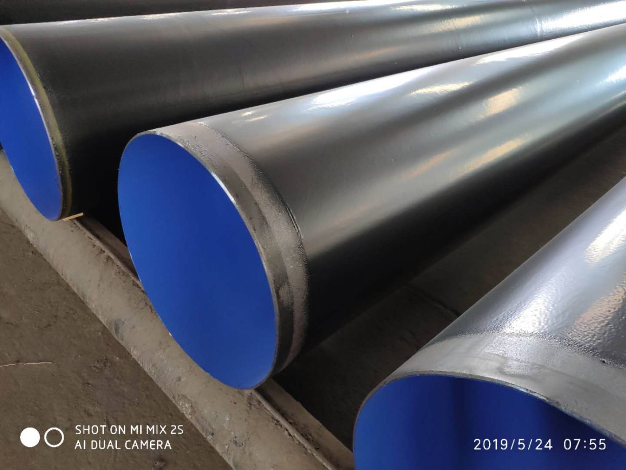
This pipe ensures minimal maintenance intervention, maximum throughput efficiency, and decades of reliable, safe operation, protecting both your investment and the environment. It is, quite simply, the assurance of endurance beneath the surface.
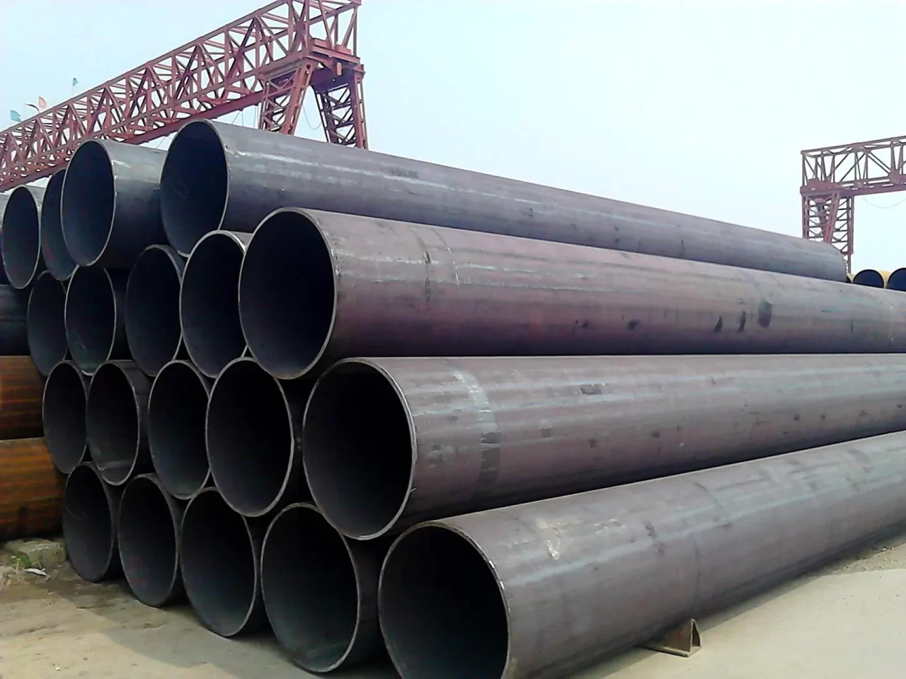
The range of steel grades under the **EN 10219-1** standard—from the dependable **S235JRH** through the versatile **S355JOH/JEH** to the high-performance **S460MH**—provides the essential material solution for every deep foundation challenge. This European standard guarantees not only high **Mechanical Properties** (Yield Strength up to 460 MPa) but also critical **Impact Toughness** ($\text{J0}/\text{J2}$) and superior **Weldability** through strict control of the **Carbon Equivalent**.
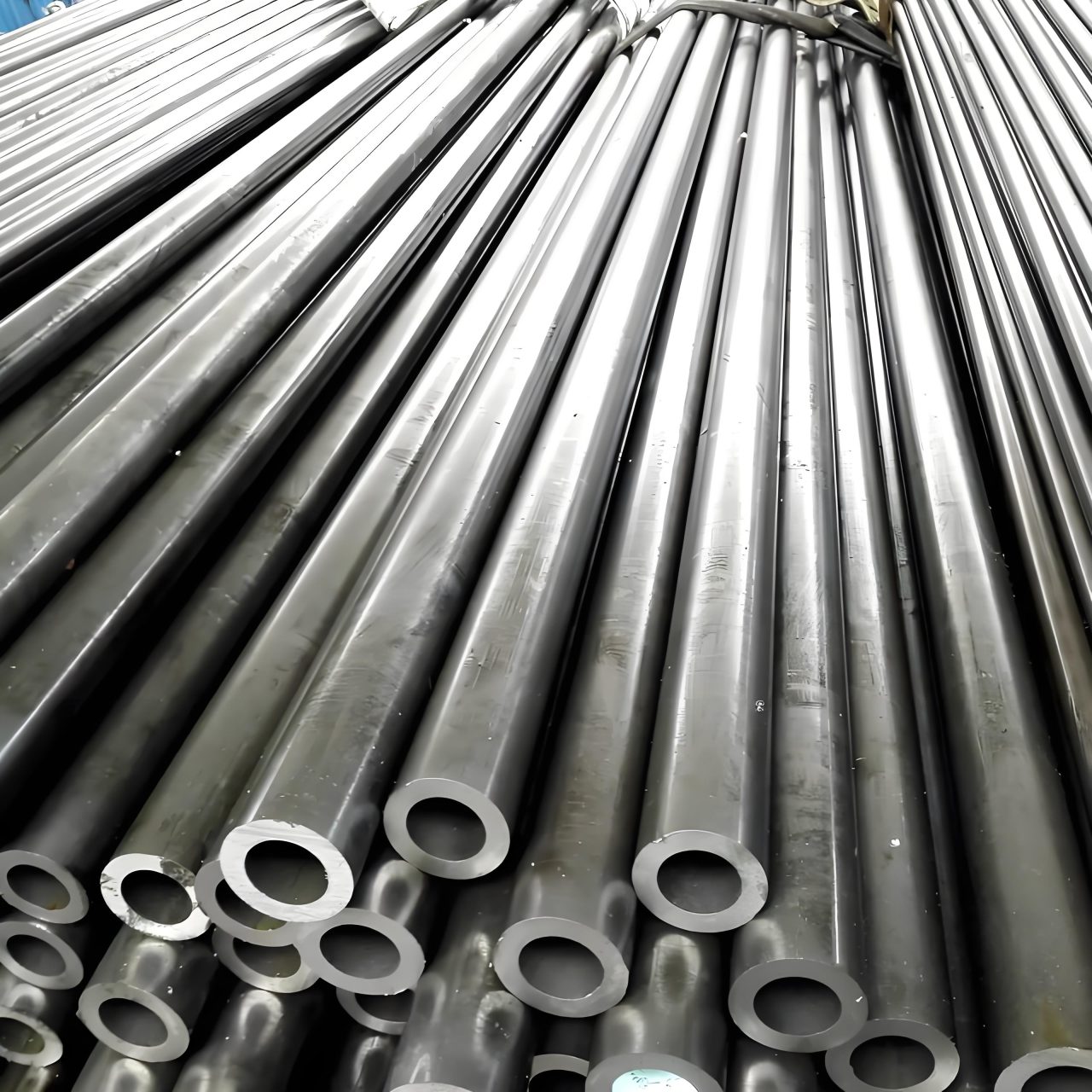
Epilogue: A334 tubes, alloyed antarctics of the line, orchestrate chill—comps cohesive, dims deft, strengths steadfast—eternal envoys of energy's equator.
Coda: TP321 tubes, alloyed aegis of the blaze, orchestrate superheat—compositions cohesive, dimensions deft, strengths steadfast—eternal emissaries of energy's ember.
ERW BLACK Pipes. Electric Resistance Welded (ERW) Pipes are manufactured from Hot Rolled Coils / Slits. All the incoming coils are verified based on the test certificate received from steel mill for their chemistry and mechanical properties. ERW pipe is cold-formed into a cylindrical shape, not hot-formed.
Seamless pipe is manufactured by extruding the metal to the desired length; therefore ERW pipe have a welded joint in its cross-section, while seamless pipe does not have any joint in its cross-section through-out its length. In Seamless pipe, there are no welding or joints and is manufactured from solid round billets.
The 3 elements of pipe dimension Dimension Standards of carbon and stainless steel pipe (ASME B36.10M & B36.19M) Pipe Size Schedule (Schedule 40 & 80 steel pipe means) Means of Nominal Pipe Size (NPS) and Nominal Diameter (DN) Steel Pipe Dimension Chart (Size chart) Pipe Weight Class Schedule (WGT)
Seamless pipes are manufactured using a piercing process, where a solid billet is heated and pierced to form a hollow tube. Welded pipes, on the other hand, are formed by joining two edges of steel plates or coils using various welding techniques.
Carbon steel pipe is highly resistant to shock and vibration which making it ideal to transport water, oil & gas and other fluids under roadways. Dimensions Size: 1/8″ to 48″ / DN6 to DN1200 Thickness: Sch 20, STD, 40, XS, 80, 120, 160, XXS Type: Seamless or welded pipe Surface: Primer, Anti rust oil, FBE, 2PE, 3LPE Coated Material: ASTM A106B, A53, API 5L B, X42, X46, X52, X56, X60, X65, X70 Service: Cutting, Beveling, Threading, Grooving, Coating, Galvanizing
Type A- Used where ample head room is available. Specific elevation is desirable. Type B- Used where headroom is limited. Head attachment is a single lug. Type C- Used where headroom is limited. Head attachment is side by side lugs