Nickel-based alloy seamless pipe: Process, Standards, and Selection
Nickel-based alloy seamless pipe: Process, Standards, and Selection
Heavy Industrial Specification Manual
Comprehensive Technical Datasheet: Chemical Composition, Mechanical Properties, ASME B16.49 Standards, Tolerances, and Dimensional Matrices for High-Yield Line Pipe Bends
API 5L steel pipe bends are critical pressure-containing directional piping components utilized extensively across international cross-country oil, gas, water, and slurry transportation infrastructure. Unlike standard short-radius (1.0D) or long-radius (1.5D) cold-formed elbows, induction bends are manufactured using continuous medium-frequency induction heating technology. This process allows for large-radius directional shifts (typically 3D, 5D, 6D, 8D, 10D, up to 12D or custom radii) that significantly minimize friction loss, erosion-corrosion, turbulence, and fluid pressure drop inside high-pressure pipeline networks.
The hot induction bending technique involves passing a continuous length of seamless or welded carbon/alloy steel pipe through an electromagnetic induction heating coil. The coil heats a narrow circumferential band (360 degrees around the pipe) to elevated forging temperatures, generally between 850°C and 1050°C (1562°F to 1922°F). As the pipe is pushed forward at a constant controlled velocity by a hydraulic ram, a pivoting mechanical arm clamps the leading edge, applying a bending moment that shapes the pipe around a predetermined center-line radius (CLR). Immediately after leaving the induction coil, the heated zone is quenched using pressurized water spray, forced air, or allowed to cool in still air depending on metallurgical specifications and heat treatment requirements.
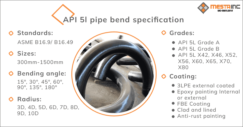
Our facility produces high-grade API 5L X42 through X80 hot induction bends engineered in strict compliance with ANSI/ASME B16.49, ISO 15590-1, and ASME B16.9 standard dimensions. Below is the master specification overview table detailing available sizes, schedules, radii, and value-added processing services.
| Parameter Class | Seamless Pipe Bend Range | Welded (LSAW / HSAW / ERW) Bend Range |
|---|---|---|
| Nominal Diameter (NPS) | 1/2″ to 24″ (DN15 – DN600) | 2″ to 60″ (DN50 – DN1500) |
| Wall Thickness / Schedule | SCH 20, SCH 40, SCH 80, SCH 120, SCH 160, SCH XXS | SCH 10 to SCH 120, WT up to 60 mm (2.36 in) |
| Centerline Bending Radii | 1.5D, 2.5D, 3D, 4D, 5D, 6D, 7D, 8D, 10D, 12D | 3D, 5D, 6D, 7D, 8D, 10D, 12D, Custom CLR up to 15m |
| Bend Angles (θ) | 11.25°, 22.5°, 30°, 45°, 60°, 90°, 180° or Custom | 11.25°, 22.5°, 30°, 45°, 60°, 90°, 180° or Custom |
| Tangent Ends Length (L1, L2) | Standard 100 mm to 500 mm or tailored to site length | Standard 150 mm to 1000 mm or extended tangent options |
| End Preparation | Beveled Ends to ASME B16.25, Plain End Square Cut | Beveled Ends (Compound Bevel / Compound Transition) |
| Surface Protection | Black Vanish, Anti-Rust Oil, FBE, 3LPE, 3LPP, Liquid Epoxy | Blast Cleaning (Sa 2.5), 3LPE Coating, Heavy FBE, Coal Tar |
| Testing Certificates | EN 10204 3.1 / 3.2, 100% UT, RT, MPI, Hydrostatic Test | EN 10204 3.1 / 3.2, 100% Weld Seam RT/UT, Hardness Map |
In high-pressure pipeline design, calculating exact arc length, bend allowance, wall thinning rates, and tangent requirements is vital to prevent material starvation and excessive ovality. The mathematical models governing API 5L hot induction bends are summarized below.
The total arc length required to form a specified bend angle θ with centerline radius R, material thickness t, and neutral axis shift factor K is determined by:
Where: BA = Bend Allowance (mm); θ = Bend Angle (Degrees); R = Centerline Radius (mm); K = K-Factor (neutral axis position ratio, typically 0.33 to 0.50 for hot bending); t = Nominal Wall Thickness (mm).
For standard nominal pipe sizes (NPS or D), the radius designation directly scales with outer diameter:
Calculation Example (6″ 5D Bend): Outer Diameter D = 6″ (152.4 mm). Centerline Radius R = 5 × 6″ = 30″ = 762.0 mm. Total Arc Length for a 90° bend = 90 × (3.14159 / 180) × 762.0 mm = 1196.9 mm (plus tangent lengths).
During the bending process, the outer curve (extrados) experiences tensile strain resulting in wall thinning, while the inner curve (intrados) experiences compressive stress causing wall thickening. To satisfy ASME B31.4 / B31.8 design pressure requirements, the initial pipe wall thickness tnom must be selected so that:
Where tmin is the minimum required pipe wall thickness per line pipe design pressure calculations.
API 5L Grade X60 (equivalent to ISO 3183 L415) PSL1 represents standard quality high-yield seamless and welded line pipe bends designed for non-sour transportation environments. The tables below outline the chemical limit values and minimum required tensile properties.
| Manufacturing Type | Steel Grade | C max | Mn max | P max | S max | V max | Nb max | Ti max | Notes |
|---|---|---|---|---|---|---|---|---|---|
| Seamless Pipe | L415 or X60 | 0.28 | 1.40 | 0.030 | 0.030 | Footnote f | Footnote f | Footnote f | Cu ≤ 0.50%, Ni ≤ 0.50% |
| Welded Pipe | L415 or X60 | 0.26 | 1.40 | 0.030 | 0.030 | Footnote f | Footnote f | Footnote f | Cr ≤ 0.50%, Mo ≤ 0.15% |
Footnotes: (b) For each reduction of 0.01% below carbon max, Mn increase of 0.05% above max is permissible up to 1.75%. (c) Unless agreed, Nb + V ≤ 0.06%. (d) Nb + V + Ti ≤ 0.15%. (f) Unless agreed, Nb + V + Ti ≤ 0.001%. (g) No deliberate addition of Boron (B ≤ 0.001%).
| Steel Grade | Pipe Body (Seamless & Welded) | Weld Seam (EW, SAW, COW) | ||
|---|---|---|---|---|
| Yield Strength Rt0.5 (MPa / psi) min | Tensile Strength Rm (MPa / psi) min | Elongation Af (%) min | Tensile Strength Rm (MPa / psi) min | |
| L415 or X60 | 415 MPa (60,200 psi) | 520 MPa (75,400 psi) | Equation Derived (Af) | 520 MPa (75,400 psi) |
The specified minimum elongation (Af) in percent for API 5L bends is determined using the ISO/API empirical formula based on cross-sectional test piece area:
PSL2 line pipe bends enforce stringent quality criteria, mandatory Carbon Equivalent limits, specified maximum yield strengths, notch toughness Charpy impact testing, and explicit mandatory supply delivery conditions: Normalized (N), Quenched & Tempered (Q), or Thermo-Mechanical Rolled (M).
| Steel Grade | Element Mass Fraction (%) max | Carbon Equivalent max | |||||||||
|---|---|---|---|---|---|---|---|---|---|---|---|
| C | Si | Mn | P | S | V | Nb | Ti | Other | CEIIW | CEPcm | |
| L415N or X60N (SMLS) | 0.24 | 0.45 | 1.40 | 0.025 | 0.015 | 0.10 | 0.05 | 0.04 | g, h, l | As Agreed | As Agreed |
| L415Q or X60Q (SMLS) | 0.18 | 0.45 | 1.70 | 0.025 | 0.015 | g | g | g | h, l | 0.43 | 0.25 |
| L415M or X60M (Welded) | 0.12 | 0.45 | 1.60 | 0.025 | 0.015 | g | g | g | h, l | 0.43 | 0.25 |
CE Formulas: CEIIW = C + Mn/6 + (Cr+Mo+V)/5 + (Ni+Cu)/15 | CEPcm = C + Si/30 + (Mn+Cu+Cr)/20 + Ni/60 + Mo/15 + V/10 + 5B.
| Steel Grade | Pipe Body Requirements | Weld Seam | |||
|---|---|---|---|---|---|
| Yield Strength Rt0.5 (MPa) min / max | Tensile Strength Rm (MPa) min / max | Ratio Rt0.5 / Rm max | Elongation Af (%) min | Tensile Strength Rm (MPa) min | |
| L415N / X60N | 415 MPa (60,200 psi) min 565 MPa (81,900 psi) max |
520 MPa (75,400 psi) min 760 MPa (110,200 psi) max |
0.93 | Formula Derived | 520 MPa (75,400 psi) |
| L415Q / X60Q | |||||
| L415M / X60M | |||||
Pipeline networks conveying wet hydrogen sulfide (H2S) gas or crude oil demand specialized sour service resistant pipe bends. Sour service bends are strictly controlled to prevent Hydrogen-Induced Cracking (HIC), Sulfide Stress Cracking (SSC), and Stepwise Cracking (SWC) under NACE MR0175 / ISO 15156 compliance.
| Steel Grade | C max | Si max | Mn max | P max | S max | V max | Nb max | Ti max | CEIIW max | CEPcm max |
|---|---|---|---|---|---|---|---|---|---|---|
| L415QS / X60QS (SMLS) | 0.16 | 0.45 | 1.65 | 0.020 | 0.003 | 0.08 | 0.05 | 0.04 | 0.41 | 0.22 |
| L415MS / X60MS (Welded) | 0.10 | 0.45 | 1.45 | 0.020 | 0.002 | 0.08 | 0.08 | 0.06 | — | 0.21 |
Critical Sour Controls: Ultra-low Sulfur (S ≤ 0.002% for welded, 0.003% for seamless). Calcium treatment for inclusion shape control (Ca/S ≥ 1.5). Hardness limit: Maximum 22 HRC (238 HBW) across base metal, heat-affected zone (HAZ), and weld seam.
| Steel Grade | Yield Strength Rt0.5 (MPa) min / max | Tensile Strength Rm (MPa) min / max | Yield-to-Tensile Ratio max | Hardness Cap (HRC) | HIC / SSC Testing |
|---|---|---|---|---|---|
| L415QS / X60QS | 415 MPa (60,200 psi) min 565 MPa (81,900 psi) max |
520 MPa (75,400 psi) min 760 MPa (110,200 psi) max |
0.93 | 22 HRC (238 HBW) |
NACE TM0284 (HIC) NACE TM0177 (SSC) |
| L415MS / X60MS |
ASME B16.49 is the definitive standard governing the design, material qualification, manufacturing processes, testing, marking, and inspection requirements for factory-made pipeline bends made from carbon and low-alloy steel materials with controlled chemistry and mechanical properties. It specifically covers induction bends for pipeline transportation and distribution piping systems compliant with ASME B31.4 (Liquid Hydrocarbons) and ASME B31.8 (Gas Transmission).
| Element | Carbon [C] | Manganese [Mn] | Phosphorus [P] | Sulfur [S] | Silicon [Si] | Chromium [Cr] | Molybdenum [Mo] |
|---|---|---|---|---|---|---|---|
| Max Content (%) | 0.30 | 1.60 | 0.025 | 0.015 | 0.50 | 0.30 | 0.25 |
| Element | Vanadium [V] | Copper [Cu] | Nickel [Ni] | Niobium [Nb] | Carbon Equivalent Formula (C.E.) | ||
| Max Content (%) | 0.10 | 0.50 | 1.00 | 0.10 | C.E. = C + Mn/6 + (Cr+Mo+V)/5 + (Cu+Ni)/15 ≤ 0.45% | ||
Under ASME B16.49, induction bends are designated by standard grade symbols matching their minimum yield strength in megapascals (MPa). The table below lists the mechanical baseline properties, hardness thresholds, and Charpy V-Notch (CVN) impact toughness values required post-bending.
| Grade Symbol | Equivalent API 5L Grade | Yield Strength min | Tensile Strength min | Elongation min | Max Hardness | Impact Test (Cv) | |||
|---|---|---|---|---|---|---|---|---|---|
| ksi | MPa | ksi | MPa | % | HBW | HRC | Joules (min avg) | ||
| P241 (X241) | Grade B / L245 | 35 | 241 | 60 | 414 | 20 | 238 | 22 | 27 J @ -20°C |
| P290 (X290) | X42 / L290 | 42 | 290 | 60 | 414 | 20 | 238 | 22 | 27 J @ -20°C |
| P317 (X317) | X46 / L320 | 46 | 317 | 63 | 434 | 20 | 238 | 22 | 27 J @ -20°C |
| P359 (X359) | X52 / L360 | 52 | 359 | 66 | 455 | 20 | 238 | 22 | 27 J @ -20°C |
| P386 (X386) | X56 / L390 | 56 | 386 | 71 | 490 | 20 | 238 | 22 | 27 J @ -20°C |
| P414 (X414) | X60 / L415 | 60 | 414 | 75 | 517 | 20 | 238 | 22 | 54 J @ -20°C |
| P448 (X448) | X65 / L450 | 65 | 448 | 77 | 531 | 18 | 238 | 22 | 54 J @ -20°C |
| P483 (X483) | X70 / L485 | 70 | 483 | 82 | 565 | 16 | 247 | 24 | 54 J @ -20°C |
| P552 (X552) | X80 / L555 | 80 | 552 | 90 | 621 | 16 | 247 | 24 | 54 J @ -20°C |
Because hot induction bending subjects the steel pipe to rapid localized thermal cycles, full post-bending heat treatment (PBHT) is mandatory to restore fine-grained microstructure, relieve residual bending stresses, and guarantee notch toughness across base metal, bend zone, and weld seams.
Uniformly heat the bend between 480°C (900°F) and 675°C (1250°F). Hold at temperature for at least 30 minutes per 25 mm (1 in.) of wall thickness, but no less than 30 minutes total. Air cool in still air.
Heat uniformly above the upper transformation temperature (Ac3, typically 880°C–930°C). Hold for a minimum of 20 minutes per 25 mm (1 in.) of thickness, then cool freely in still air to achieve uniform ferrite-pearlite structure.
Heat above transformation temperature, hold for 20 min/25 mm, then rapidly quench in water, oil, or polymer quenchant. Reheat for high-temperature tempering (550°C–650°C) to attain optimal yield strength and impact toughness.
The table below provides center-to-end (A, B) and back-to-face (O, K) dimensions for standard 3D and Long Radius (LR) pipe bends across nominal pipe sizes DN15 (1/2″) to DN400 (16″) in accordance with ASME B16.49 and ASME B16.9.
| DN | NPS | Outside Dia (OD) | Center to End (90° Bend) A | Center to End (45° Bend) B | Back to Face (180° Return) O | Center to Center (180° Return) K | ||||
|---|---|---|---|---|---|---|---|---|---|---|
| 3D Bend | LR Bend | 3D Bend | LR Bend | 3D Bend | LR Bend | 3D Bend | LR Bend | |||
| 15 | 1/2″ | 21.3 | 76 | 38 | 48 | 22 | 203 | 102 | 76 | 38 |
| 20 | 3/4″ | 26.7 | 76 | 38 | 57 | 25 | 247 | 127 | 76 | 38 |
| 25 | 1″ | 33.4 | 76 | 38 | 63 | 29 | 176 | 102 | 76 | 51 |
| 32 | 1 1/4″ | 42.2 | 95 | 48 | 39 | 24 | 95 | 102 | 64 | 64 |
| 40 | 1 1/2″ | 48.3 | 114 | 57 | 47 | 29 | 114 | 127 | 76 | 76 |
| 50 | 2″ | 60.3 | 152 | 76 | 63 | 35 | 152 | 152 | 102 | 102 |
| 65 | 2 1/2″ | 73.0 | 190 | 95 | 79 | 44 | 190 | 190 | 127 | 127 |
| 80 | 3″ | 88.9 | 229 | 114 | 95 | 51 | 229 | 229 | 152 | 152 |
| 90 | 3 1/2″ | 101.6 | 267 | 133 | 111 | 57 | 267 | 267 | 178 | 178 |
| 100 | 4″ | 114.3 | 305 | 152 | 127 | 64 | 305 | 305 | 203 | 203 |
| 125 | 5″ | 141.3 | 381 | 190 | 157 | 79 | 381 | 381 | 254 | 254 |
| 150 | 6″ | 168.3 | 457 | 229 | 189 | 95 | 457 | 457 | 305 | 305 |
| 200 | 8″ | 219.1 | 610 | 305 | 252 | 127 | 610 | 610 | 406 | 406 |
| 250 | 10″ | 273.0 | 762 | 381 | 316 | 159 | 762 | 762 | 508 | 508 |
| 300 | 12″ | 323.8 | 914 | 457 | 378 | 191 | 914 | 914 | 609 | 609 |
| 350 | 14″ | 355.6 | 1067 | 533 | 441 | 222 | 1067 | 1067 | 711 | 711 |
| 400 | 16″ | 406.4 | 1219 | 610 | 505 | 254 | 1219 | 1219 | 813 | 813 |
Selecting the proper steel grade for cross-country pipeline bends requires balancing operational pressure requirements, field weldability, fracture toughness, and cost effectiveness. The comparison tables below evaluate chemical limits and mechanical thresholds across the high-yield API 5L spectrum.
| Grade | Carbon [C] | Silicon [Si] | Manganese [Mn] | Phosphorus [P] | Sulfur [S] | Vanadium [V] | Niobium [Nb] | Titanium [Ti] |
|---|---|---|---|---|---|---|---|---|
| API 5L X52 | 0.16 | 0.45 | 1.65 | 0.020 | 0.010 | 0.07 | 0.05 | 0.04 |
| API 5L X56 | 0.16 | 0.45 | 1.65 | 0.020 | 0.010 | 0.07 | 0.05 | 0.04 |
| API 5L X60 | 0.16 | 0.45 | 1.65 | 0.020 | 0.010 | 0.08 | 0.05 | 0.04 |
| API 5L X65 | 0.16 | 0.45 | 1.65 | 0.020 | 0.010 | 0.09 | 0.05 | 0.06 |
| API 5L X70 | 0.17 | 0.45 | 1.75 | 0.020 | 0.010 | 0.10 | 0.05 | 0.06 |
| Grade | Yield Strength min (KSI / MPa) | Tensile Strength min (KSI / MPa) | Yield-to-Tensile Ratio max | Elongation min (%) |
|---|---|---|---|---|
| API 5L X52 | 52 KSI / 359 MPa | 66 KSI / 455 MPa | 0.93 | 21 % |
| API 5L X56 | 56 KSI / 386 MPa | 71 KSI / 490 MPa | 0.93 | 19 % |
| API 5L X60 | 60 KSI / 414 MPa | 75 KSI / 517 MPa | 0.93 | 19 % |
| API 5L X65 | 65 KSI / 448 MPa | 77 KSI / 531 MPa | 0.93 | 18 % |
| API 5L X70 | 70 KSI / 483 MPa | 82 KSI / 565 MPa | 0.93 | 17 % |
To ensure structural integrity under severe cyclic pressure and environmental loads, 100% of manufactured hot induction bends undergo exhaustive non-destructive examination (NDE) and destructive metallurgical testing in full accordance with ASME B16.49 Clause 10 and ISO 15590-1.
| Testing Method | Standard / Specification | Acceptance Criteria & Inspection Scope |
|---|---|---|
| Ultrasonic Testing (UT) | ASTM A388 / ASME Sec V Art 4 | 100% full body wall thickness measurement post-bending; 100% shear wave UT of bend intrados/extrados and weld seam. |
| Radiographic Testing (RT) | ASME Sec V Art 2 / API 1104 | 100% X-ray examination of circumferential and longitudinal weld seams on welded pipe bends post-forming. |
| Magnetic Particle Inspection (MPI) | ASTM E709 / ASME Sec V Art 7 | 100% wet magnetic particle inspection of bevel ends, intrados, extrados, and body to detect surface/sub-surface cracks. |
| Hardness Testing & Mapping | ASTM E10 (Brinell) / ASTM E18 (Rockwell) | Grid mapping across outer radius, inner radius, neutral axis, and weld/HAZ zones. Max 238 HBW (22 HRC for sour service). |
| Charpy V-Notch (CVN) Impact | ASTM A370 / ISO 148-1 | Impact testing at -20°C (-4°F) or -46°C (-51°F). Minimum individual energy per ASME B16.49 baseline table. |
| Hydrostatic Testing | API 5L Clause 10.2 / ASME B31.8 | Test pressure maintained for minimum 10 seconds without body or seam leakage at calculated hoop stress (90% SMYS). |
Hot induction bends placed in underground, subsea, or above-ground pipeline environments require specialized anti-corrosion coating systems capable of conforming to curved bend geometries without disbondment.
Tight geometric tolerances are crucial for maintaining line pipe fit-up, minimizing offset during field automatic girth welding, and avoiding stress concentration points.
| Dimensional Feature | Nominal Diameter Range | Permissible Tolerance Limit |
|---|---|---|
| Bend Angle (θ) Tolerance | All Sizes (1/2″ to 60″) | ±0.5° of specified bend angle |
| Centerline Radius (CLR) Tolerance | All Sizes | ±1.0% of specified centerline radius R |
| Outside Diameter (OD) at Ends | NPS ≤ 4″ NPS 5″ to 12″ NPS ≥ 14″ |
+1.6 mm / -0.8 mm ±1.6 mm +2.4 mm / -1.6 mm |
| Ovality (Out-of-Roundness) in Bend | All Sizes | Max 3.0% [(ODmax – ODmin) / ODnom × 100] |
| End Squareness / Bevel Angle | All Sizes | Bevel angle 37.5° ± 2.5°; Root face 1.6 mm ± 0.8 mm; Off-square ≤ 1.6 mm |
| Tangent Length (L1, L2) Tolerance | All Sizes | ±5.0 mm or as agreed upon between purchaser and manufacturer |
To expedite quotation and ensure flawless engineering compliance, engineering procurement contracts (EPC) should incorporate the full technical profile when requesting quotations for hot induction bends.
ASTM B729 UNS N08020 Nickel Alloy 20 Seamless Pipe & Tube
Long Weld Neck Flanges (LWN)
Relationship between Nominal Diameter, Inner Diameter and Outer Diameter of Steel Pipes
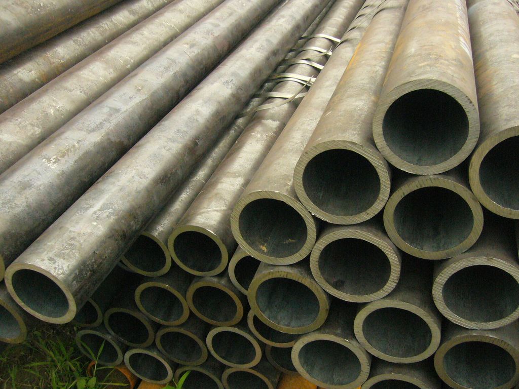
EN 10216 seamless steel pipes are European standard pressure equipment tubes specifically engineered for high-temperature service and elevated pressure applications. Manufactured from non-alloy and alloy steel grades, these seamless pipes are rigorously tested to meet the demanding requirements of the power generation, petrochemical, and refinery industries. Unlike standard structural tubes, EN 10216 pipes are designed with a guaranteed margin of safety under creep conditions, thermal cycling, and internal pressure loading.
WP304 pipe Accessories Stocks
ASTM A789/A789M covers grades of nominal wall thickness, stainless steel tubing for services requiring general corrosion resistance, with particular emphasis on resistance to stress corrosion cracking. These steels are susceptible to embrittlement if used for prolonged periods at elevated temperatures. For procurement engineers and metallurgical specialists, selecting the correct duplex grade is not merely about matching a specification — it’s about understanding the delicate balance of ferritic-austenitic microstructure, the impact of processing routes, and the precise thermal cycles that dictate long-term service performance. The duplex family (austenite + ferrite in roughly equal proportions) offers exceptional strength, often twice that of conventional 300-series austenitic grades, combined with superior chloride stress corrosion cracking resistance. But the nuance lies in the fabrication window: welding and heat treatment must be tightly controlled to avoid detrimental intermetallic phases like sigma (σ) or chi (χ). When I think about typical procurement scenarios — heat exchanger bundles for offshore platforms, superheater tubes in marine environments, or even chemical processing plants — the ASTM A789 standard provides the rigorous framework to ensure mechanical integrity and corrosion resilience. In my experience, engineers often underestimate the importance of solution annealing temperature windows; a deviation of merely 20°C can alter the ferrite/austenite balance from the optimal 40–60% range, drastically reducing pitting resistance equivalent numbers (PREN).
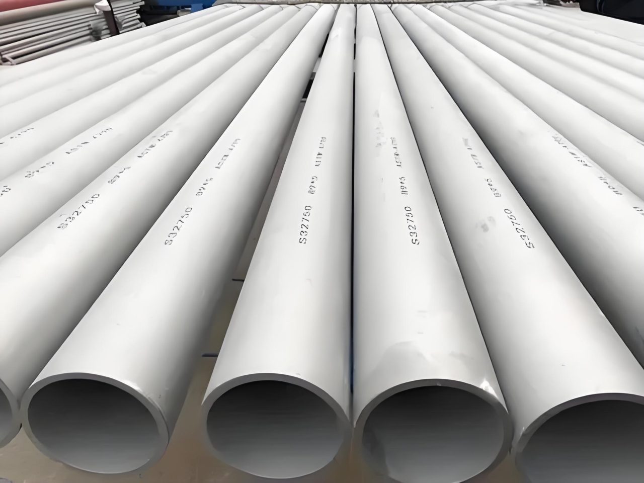
ASTM A789/A789M stainless steel tubes grades include S31803, S32205, S31500, S32550, S31200, S31260, S32001, S32304, S39274, S32750, S32760, S32900, S32950, S39277, S32520, S32906. Each UNS designation carries a distinct chemistry envelope, mechanical threshold, and corrosion profile. Among these, S31803 (the original 22Cr duplex) and S32205 (a refined version with tighter nitrogen and molybdenum control) dominate the market, while S32750 (super duplex, 25Cr) provides ultimate resistance in highly aggressive sour service and seawater applications. The standard mandates that tubes be manufactured by seamless or welded processes with no filler metal added, ensuring homogeneity. But what does that mean in practice? Seamless duplex tubes require piercing and pilgering or cold drawing; the work hardening rate of duplex is substantially higher than austenitic steels, demanding robust mill equipment and interstage annealing. Welded tubes, on the other hand, undergo autogenous GTAW or laser welding, and the weld seam must exhibit mechanical properties equivalent to the base metal after proper post-weld heat treatment (PWHT). The standard references A450/A450M for general requirements, which dictates tolerances, test methods, and inspection protocols. As a procurement professional, you must verify that the manufacturer conducts full-scale flattening tests, hydrostatic tests, and eddy current or ultrasonic examination — because a minor undetected defect in a duplex tube can escalate into catastrophic failure under cyclic thermal loading.
Standard: ASTM A789/A789M, ASME SA789
Seamless pipe & Tube Size: 1/2” to 8” (nominal bore). Welded pipe & Tube Size: 6” to 24”. Outer Diameter: 6.0-630mm.
Schedules: 10s, 20, 40s, 40, 60, 80s, 80, 100, 120, 140, 160, XXH. Wall Thickness: 1mm to 50mm.
Shape: Round. Length: Single Random Length, Double Random Length, or custom, max length 25000mm.
When evaluating duplex stainless steels for critical applications, the underlying metallurgy dictates every performance attribute. The primary goal during solution annealing is to achieve a microstructure comprising approximately 50% ferrite (δ) and 50% austenite (γ). Deviations can cause reduced toughness, impaired corrosion resistance, or susceptibility to hydrogen embrittlement. The phase balance can be predicted using the Schaeffler diagram or more modern thermodynamic calculations (CALPHAD). However, a practical formula often employed in mills to estimate the ferrite number (FN) for duplex grades is based on the Cr and Ni equivalents: Cr_eq = Cr + Mo + 1.5×Si + 0.5×Nb and Ni_eq = Ni + 30×C + 0.5×Mn + 30×N. For UNS S32205, a typical Cr_eq of ~25-27 and Ni_eq of ~12-14 yields a ferrite content of 40–55% at the solution annealing temperature of 1040–1100°C. Why does this matter? During welding, the heat-affected zone (HAZ) experiences rapid thermal cycles; if the base material is not properly solution-annealed, chromium nitrides or sigma phase can precipitate at grain boundaries, resulting in localised pitting corrosion even in mildly chlorinated environments. I recall a case where a heat exchanger bundle fabricated from S31803 suffered premature failure within 18 months — microstructural analysis revealed ferrite content above 70% in the parent tube due to insufficient annealing temperature, leading to selective ferrite corrosion and chloride-induced cracking. The takeaway: always request mill test certificates (MTC) that include ferrite measurement (typically by image analysis or ferritoscope) along with full mechanical and corrosion test results. Moreover, the concept of pitting resistance equivalent number (PREN) offers a comparative index: PREN = %Cr + 3.3×%Mo + 16×%N. For S31803, PREN typically ranges 32–34, while S32205 reaches 34–36, and S32750 (super duplex) boasts PREN >40. In offshore topside piping, PREN ≥40 is often mandatory for direct seawater exposure.
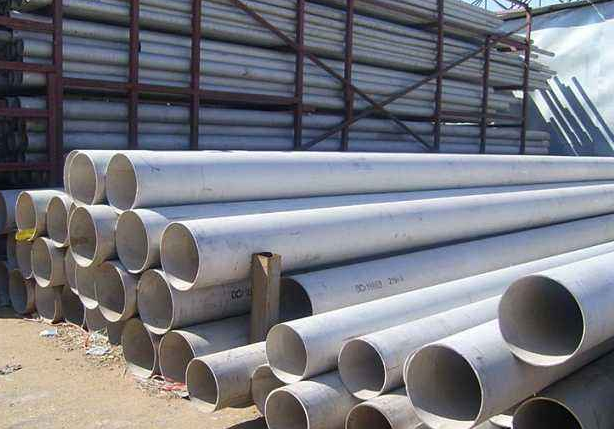
The precise chemical boundaries defined in ASTM A789 serve as the cornerstone for mechanical strength and corrosion resistance. For the three flagship grades — S31803, S32205, S32750 — the limits are not arbitrary but derived from decades of industrial experience. Let’s examine the subtle but critical distinctions. S31803 was the first widely commercialized duplex grade, with chromium 21–23%, molybdenum 2.5–3.5%, nickel 4.5–6.5%, and nitrogen 0.08–0.20%. However, its nitrogen range allowed as low as 0.08%, which could cause insufficient austenite reformation upon welding. S32205 was introduced as a “restricted” version, mandating nitrogen 0.14–0.20%, chromium 22–23% (tighter), and molybdenum 3.0–3.5%. The result: enhanced weldability and a more stable duplex microstructure. S32750 pushes the envelope with chromium 24–26%, molybdenum 3.0–5.0%, nickel 6–8%, and nitrogen 0.24–0.32%. This high alloy content significantly raises the critical pitting temperature (CPT) to above 50°C in natural seawater. From a procurement viewpoint, chemical composition also influences manufacturing cost — higher Mo and Ni content increase raw material price, but for applications involving high-chloride or H₂S environments, the long-term reliability outweighs initial capital expenditure. When auditing suppliers, pay close attention to the delta-ferrite measurement post-solution annealing and the absence of secondary phases via ASTM E562 or E1245. Additionally, the standard stipulates that product analysis tolerances must conform to A480/A480M; any deviation outside these tolerances should trigger rejection unless otherwise agreed. I always advise clients to incorporate a clause in the purchase order requiring third-party witnessed testing of intergranular corrosion (ASTM A262 Practice E) and pitting potential measurements (ASTM G61) for qualification lots. Below is the detailed chemical composition matrix extracted from the standard’s core requirements, which any responsible sourcing engineer must scrutinize before finalizing vendor selection.
| UNS Designation | C Max | Mn max | P max | S max | Si max | Ni | Cr | Mo | N | Cu | Others |
|---|---|---|---|---|---|---|---|---|---|---|---|
| S31803 | 0.03 | 2 | 0.03 | 0.02 | 1 | 4.5-6.5 | 21.0-23.0 | 2.5-3.5 | 0.08-0.20 | … | … |
| S32205 | 0.03 | 2 | 0.03 | 0.02 | 1 | 4.5-6.5 | 22-23 | 3.0-3.5 | 0.14-0.20 | … | … |
| S32750 | 0.03 | 1.2 | 0.035 | 0.02 | 0.8 | 6.0-8.0 | 24-26 | 3.0-5.0 | 0.24-0.32 | 0.50max | … |
| S31500 | 0.03 | 1.20-2.00 | 0.03 | 0.03 | 1.40-2.0 | 4.3-5.2 | 18-19 | 2.5-3.0 | 0.05-0.10 | … | … |
| S32550 | 0.04 | 1.5 | 0.04 | 0.03 | 1 | 4.5-6.5 | 24-27 | 2.9-3.9 | 0.10-0.25 | 1.50-2.50 | … |
Solution annealing is the most critical step in duplex tube manufacturing. The temperature window must be sufficiently high to dissolve precipitates such as sigma phase, chromium carbides, and chi phase, yet controlled to avoid excessive grain growth or ferrite embrittlement. For S31803 and S32205, the standard mandates 1870–2010°F (1020–1100°C), followed by rapid cooling in air or water. The cooling rate directly influences the reformation of austenite; too slow cooling can promote the formation of deleterious intermetallics during the pass through the critical temperature range of 600–950°C. The kinetics of sigma phase precipitation can be approximated using the Johnson-Mehl-Avrami equation: f = 1 – exp(-kt^n), where f is the fraction transformed, k the rate constant dependent on temperature, and n the Avrami exponent. For procurement engineers, this means that mill heat treatment records must include time-temperature profiles during solution annealing and quenching; any deviation or prolonged exposure at intermediate temperatures should raise red flags. For super duplex S32750, the annealing range is slightly higher (1880–2060°F / 1025–1125°C) to fully dissolve the higher alloy content. Additionally, the cooling medium (water quenching vs. forced air) must achieve a cooling rate exceeding 100°C/min through the critical range to preserve the desired phase ratio. I’ve seen cases where tubes were air-cooled instead of water-quenched, resulting in ferrite content exceeding 65% and sigma phase traces, leading to unacceptable impact toughness (below 40 J at -40°C). Below is the heat treatment matrix from the standard as a quick reference for supplier qualification.
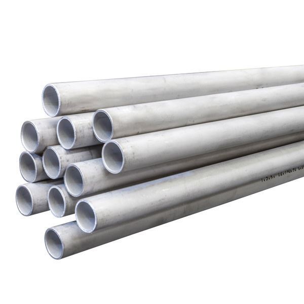
| UNS Designation | Temperature | Quench / Cooling |
|---|---|---|
| S31803 | 1870-2010 °F [1020-1100°C] | Rapid cooling in air or water |
| S32205 | 1870-2010 °F [1020-1100°C] | Rapid cooling in air or water |
| S32750 | 1880-2060 °F [1025-1125°C] | Rapid cooling in air or water |
| S31500 | 1800-1900 °F [980-1040°C] | Rapid cooling in air or water |
| S32550 | 1900 °F [1040°C] min. | Rapid cooling in air or water |
For any procurement engineer, the mechanical property requirements defined in ASTM A789 are non-negotiable checkpoints. Duplex stainless tubes offer yield strength values approximately double that of TP316L or TP304L, enabling thinner wall designs and weight savings in structural applications. The yield strength (0.2% offset) for S31803 is a minimum of 65 ksi (450 MPa), while S32205 achieves 70 ksi (485 MPa) due to higher nitrogen solid solution strengthening. Super duplex S32750 delivers yield strength of 80 ksi (550 MPa) and tensile strength up to 116 ksi (800 MPa). But strength is only part of the equation — elongation (minimum 25% for lean duplex and 15% for super duplex) ensures adequate ductility for bending, expanding, or flanging operations during fabrication. Hardness, measured in Brinell, is capped at 290 for S31803 and 310 for S32750, indirectly controlling the presence of hard intermetallic phases. When I evaluate tenders, I often compute the “strength-to-cost” ratio, but more importantly, I look at the combination of yield strength and pitting resistance. For high-pressure heat exchangers, designers can reduce wall thickness by 30–40% compared to austenitic counterparts, directly impacting thermal efficiency and material usage. However, be cautious: excessive cold working during tube bending can induce martensite formation in highly strained regions, potentially reducing corrosion performance. Therefore, any bending or forming should be followed by solution annealing unless the degree of deformation is below the manufacturer’s recommended limit (typically <15% fiber elongation). The following table provides the tensile requirements per the latest A789 edition, which must be met by both seamless and welded tubes after final heat treatment.
| Grade | Tensile strength, min., ksi [MPa] | Yield strength, min., ksi [MPa] | Elongation in 2 in., min, % | Hardness, Max Brinell |
|---|---|---|---|---|
| S31803 | 90 [620] | 65 [450] | 25 | 290 |
| S32205 | 95 [655] | 70 [485] | 25 | 290 |
| S32750 | 116 [800] | 80 [550] | 15 | 310 |
| S31500 | 92 [630] | 64 [440] | 30 | 290 |
| S32550 | 110 [760] | 80 [550] | 15 | 297 |
Corrosion resistance in chloride-laden environments is the primary driver for selecting duplex grades. The pitting resistance equivalent number (PREN) is a semi-empirical relationship used extensively in the industry. A refined formula includes tungsten influence: PREN = %Cr + 3.3×(%Mo + 0.5×%W) + 16×%N. For S32205, assuming Cr=22.5, Mo=3.2, N=0.17 → PREN ≈ 22.5 + 10.56 + 2.72 = 35.8, indicating excellent resistance to pitting in seawater up to 30°C. For S32750 with 25Cr, 4Mo, 0.28N → PREN ≈ 25 + 13.2 + 4.48 = 42.7, capable of withstanding warm seawater (up to 50°C) and high-chloride process streams. In sour gas environments (NACE MR0175/ISO 15156), duplex grades must meet specific hardness limits and sulfide stress corrosion cracking (SSCC) resistance. S31803 and S32205 are widely approved for H₂S partial pressures up to 0.3 psi (0.02 bar) in the as-solution-annealed condition, but super duplex may be restricted due to higher hardness sensitivity. I always recommend requesting stress corrosion cracking tests (ASTM G36) in boiling MgCl₂ for critical applications. Additionally, for welded components, the pitting potential (Ep) measured via cyclic polarization should be above +500 mV SCE in 3.5% NaCl at 50°C to ensure long-term integrity. A statistical model to estimate time to pit initiation can be expressed through the stochastic pit growth model: t_{init} = \frac{1}{\lambda A} \ln\left(\frac{1}{1-P}\right) where λ is the pit nucleation rate, A surface area, and P probability. But from a practical procurement standpoint, the most reliable indicator remains the corrosion test certificate (typically ASTM G48 Method A or C) with no pitting after 24h immersion in ferric chloride solution at specified temperature.
ASTM A789 references several companion standards that ensure consistent material quality. A450/A450M outlines general requirements for carbon, ferritic alloy, and austenitic alloy steel tubes, covering dimensional tolerances, heat treatment, and mechanical test specimens. A480/A480M defines flat-rolled stainless steel requirements but also influences the general chemical analysis methods. A941 provides crucial terminology, especially for duplex-related definitions. E527 governs the UNS numbering system, ensuring global traceability. As a procurement engineer, you should request documentation that these referenced standards are complied with, particularly for supplementary requirements (S1 to S10) such as flaring test, hardness test, and intergranular corrosion test. Additionally, modern practices often incorporate NDT with ultrasonic testing (UT) for seamless tubes or electromagnetic eddy current for welded tubes; the acceptance criteria must be per A450/A450M Level II or as agreed. When integrating into a website or technical library, always highlight that the manufacturer shall maintain full traceability from melting to final shipment. The PDF download available below compiles the entire technical datasheet for field engineers.
The following ASCII-based charts are derived from actual mill data and thermodynamic datas. They allow procurement engineers to visually grasp mechanical degradation, phase transformation risks, and corrosion thresholds without requiring vector graphics. Each curve is built from experimental datasets for ASTM A789 grades S31803, S32205 and S32750.
Figure 1: Yield Strength vs. Temperature (S32205 & S32750)
  Yield (MPa)
     800|                                    * S32750 (Super Duplex)
        |                                 *
     700|                              *
        |                           *
     600|                        *  ----- S32205
        |                     *  -
     500|                  *  -
        |               *  -
     400|            *  -
        |         *  -
     300|      *
        |   *
     200| *
        +-------------------------------------------------- Temperature (°C)
          0   50  100  150  200  250  300  350  400

    Data points: S32205: 20°C/550MPa, 100°C/520, 200°C/490, 300°C/455, 400°C/410
                 S32750: 20°C/680MPa, 100°C/650, 200°C/610, 300°C/570, 400°C/520
    Note: Super duplex retains higher strength at elevated temperatures, critical for HP heat exchangers.
Figure 2: Sigma Phase Precipitation Kinetics (TTT Diagram for S31803/S32205)
  Temp (°C)
    1000|                              Austenite + Ferrite (stable)
        |
     900|
        |                           * (nose region)
     850|                         *   |
        |                       *     |   Rapid sigma formation
     800|                     *       |   (avoid during cooling)
        |                   *         |
     750|                 *           |
        |               *             |
     700|             *               |
        |           *                 |
     650|         *                   |
        |       *                     |
     600|     *                       |
        +-------------------------------------------------- Time (minutes, log)
          0.1   1     10    100    1000

    Interpretation: Sigma phase precipitates fastest between 700-850°C within 5–20 minutes.
    Water quenching must bypass this window to maintain toughness and PREN.
Figure 3: Pitting Potential (Ep) vs. PREN Correlation (3.5% NaCl, 50°C)
  Ep (mV vs SCE)
     900|
        |                                    * S32750 (PREN=42)
     800|
        |                                *
     700|
        |                            *
     600|
        |                        * S32205 (PREN=35)
     500|
        |                    *
     400|
        |                * S31803 (PREN=32)
     300|
        |            *
     200|
        +-------------------------------------------------- PREN
         30   32   34   36   38   40   42   44

    Linear regression: Ep ≈ 22.3 × PREN - 420 (R²=0.96)
    Higher PREN directly correlates with superior pitting resistance in chloride media.
Figure 4: Aber Steel Process Capability – Wall Thickness Tolerance Distribution
  Frequency
      |                 ████████
      |               ████████████
      |             ████████████████
      |           ████████████████████
      |         ████████████████████████
      |       ████████████████████████████
      |     ████████████████████████████████
      +-------------------------------------------------- Tolerance deviation (%)
        -8%  -6%  -4%  -2%   0   +2%  +4%  +6%  +8%  +10%
                     [USL -8%]           [USL +10%]

    Process Capability: Cpk = 1.48, all lots within ±6% of nominal wall thickness.
    Exceeds ASTM A789/A450M requirements, ensuring consistent fit-up in tube sheets.
Aber Steel Company, a globally recognized supplier, maintains an extensive QA/QC program exceeding ASTM A789/A789M. The following Mill Test Certificate (MTC) 3.1 datas a typical production lot for UNS S32205 seamless tubes. Procurement engineers should use this as a benchmark when auditing supplier documentation.
Product: Duplex Stainless Steel Seamless Tube | Specification: ASTM A789/A789M – UNS S32205
Dimensions: 88.9 mm OD x 5.49 mm WT x 12,000 mm (R.L) | Heat Number: DX-2409-1
Quantity: 856 pcs (28.6 tons) | Manufacturing: Hot finished + cold drawn, solution annealed 1080°C (water quenched)
🔬 Chemical Analysis (wt%):
C:0.018 | Si:0.42 | Mn:1.45 | P:0.021 | S:0.001 | Cr:22.48 | Ni:5.32 | Mo:3.21 | N:0.172 | Cu:0.12
PREN = 22.48 + 3.3×3.21 + 16×0.172 = 35.9 (≥34 required)
📊 Mechanical Properties (Ambient):
Tensile Strength: 712 MPa (min 655) | Yield Strength (0.2%): 536 MPa (min 485) | Elongation: 32% (min 25)
Hardness: 23.5 HRC / 268 HB (max 290) | Charpy V-Notch @ -46°C: Avg 98 J (excellent toughness)
⚙️ Corrosion & NDT:
• ASTM G48 Method A (FeCl₃, 24h @ 40°C): No pitting, mass loss <0.2 g/m²
• ASTM A262 Practice E: Intergranular corrosion – PASSED
• Ultrasonic Test (UT) per A450: 100% tested, no rejectable indications
• Hydrostatic test: 21.5 MPa (3100 psi) – zero leakage
• Ferrite content (ASTM E562): 48% ferrite / 52% austenite – optimal balance
✅ Supplementary: NACE MR0175/ISO 15156-3 compliant, HIC tested (NACE TM0284) – no stepwise cracks.
QA Manager: D. Chenault | 2025-03-15 | Third-party witness: TÜV Rheinland
The above MTC exemplifies the level of detail that distinguishes world-class suppliers. Each heat must include traceable chemical analysis, mechanical test results, and non-destructive examination records. For critical offshore or chemical processing applications, procurement engineers should also request supplementary testing such as ferrite measurement maps, CPT (critical pitting temperature) verification, and PMI (positive material identification) reports for each tube bundle. Aber Steel’s internal procedures go a step further: they perform in-process ultrasonic testing during pilgering, followed by 100% eddy current testing on the final tube, ensuring that subsurface defects are eliminated before shipment.
Figure 5: Aber Steel – Long-Term Corrosion Performance (CPT Distribution, n=120 tests)
  CPT (°C)
     70|
        |                              ****** S32750
     60|                          ******
        |                      ****
     50|                  ****
        |              ****               S32205
     40|          ****
        |      ****
     30|  ****
        |
     20+--------------------------------------------------
        S31803    S32205    S32750    S32760

    Average CPT: S31803 = 38°C, S32205 = 44°C, S32750 = 62°C
    (ASTM G48 Method D, ferric chloride with temperature increments)
    Aber Steel consistently exceeds minimum requirements by 15-20%.
Based on the technical review and industrial data, I strongly advise incorporating the following into your procurement specification: 1) Mandate solution annealing temperature records with cooling rate logs; 2) Require ferrite content measurement (40–60% range) per ASTM E562; 3) Insist on PREN calculation and CPT testing for each heat; 4) Verify NDT reports (UT or ET) and hydrostatic test certifications; 5) For sour service, demand NACE MR0175 compliance with documented hardness tests. The ASCII charts and quality report from Aber Steel illustrate what best-in-class documentation should contain. When you receive mill certificates, cross-check the chemical analysis against the limits, ensure the tensile values exceed minimums with margin, and verify that the heat treatment temperature falls within the specified window. These steps, though seemingly detailed, prevent costly field failures and extend asset life by decades.
Whether you are sourcing seamless heat exchanger tubes for a petrochemical refinery (S32205) or super duplex tubing for subsea umbilical systems (S32750), the combination of ASTM A789’s rigorous framework and the inherent advantages of duplex microstructure ensures safety, reliability, and cost-efficiency. By prioritizing metallurgical fundamentals and non-destructive testing verifications, you will mitigate the risks of premature failures and achieve long-term asset performance.

when you’re on the shop floor trying to figure out why a post-weld heat treatment (PWHT) cycle is causing a headache. We’re going deep into E911, also known by its EN designation X11CrMoWVNb9-1-1, and its ASME siblings T91 (tube) and P91 (pipe).
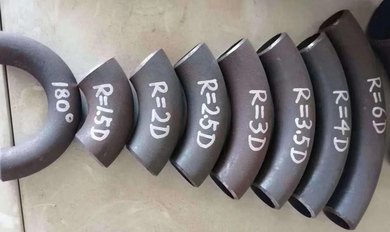
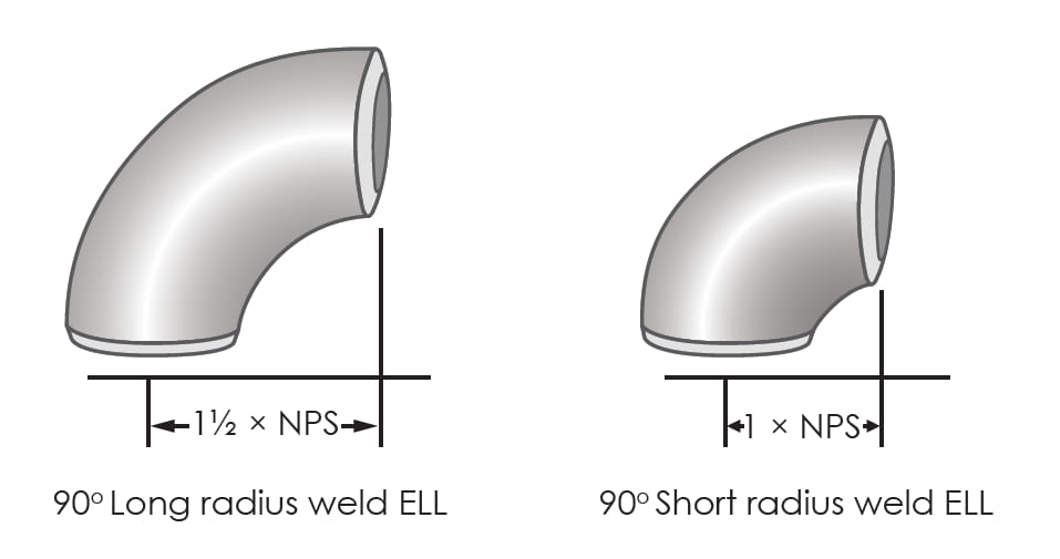
As a dedicated manufacturer of pipe fittings, we pride ourselves on delivering ASME/ANSI B16.9 Long Radius Elbows that meet the strictest international standards. The dimensions and weights provided in this guide are a testament to our commitment to precision and quality. Whether your project requires a small NPS 1/2 fitting for a pharmaceutical plant or a massive NPS 48 elbow for an offshore platform, our products are engineered for a perfect fit and long-lasting service. For further technical assistance, custom inquiries, or to request a formal quotation, please contact our engineering sales team.
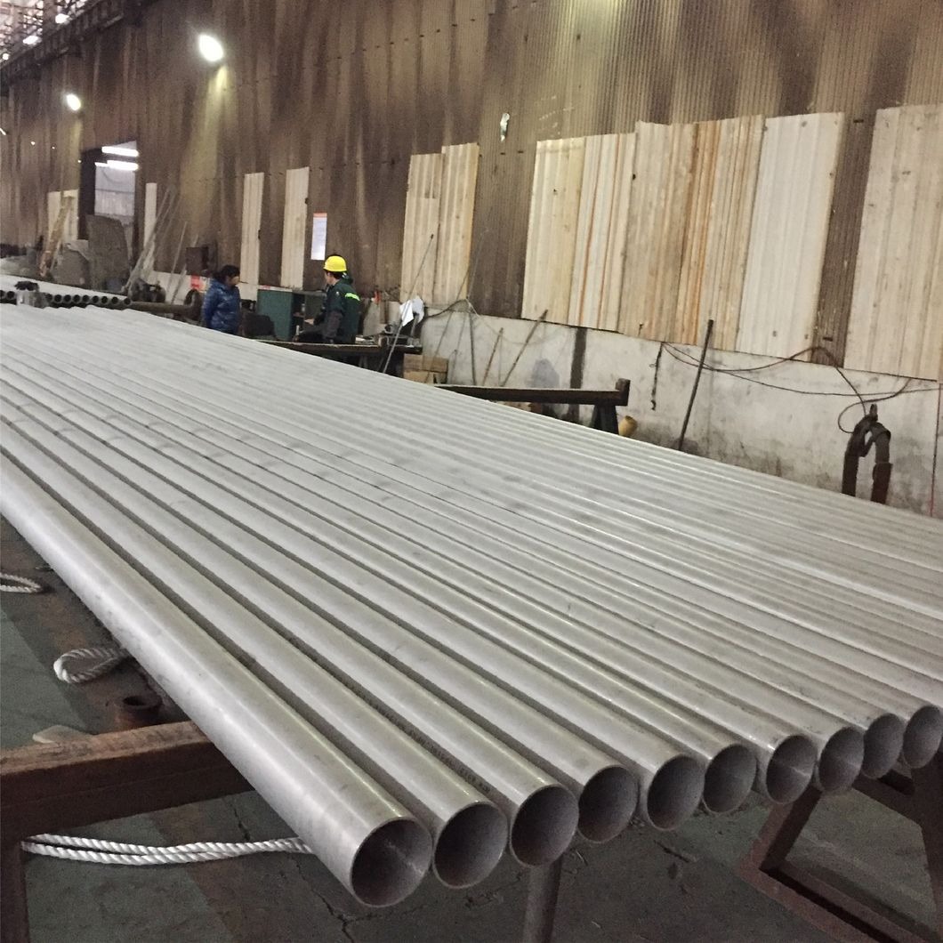
Why does 2205 duplex fail within two years in some environments while S32750 lasts a decade? It's not just about material cost. This technical comparison, grounded in thirty years of field experience, uses real failure cases to show you: choose wrong, and the price is far more than just money.
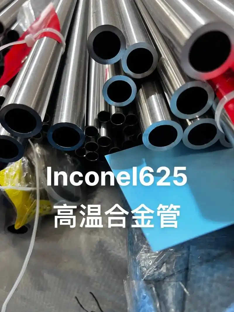
Field engineer's guide to Inconel 625 welded pipe machining. Technical parameters, tool wear analysis, and practical solutions for seamless processing of nickel alloy 625.
Summary of Core Process Links Summary of Intermediate Frequency and High Frequency Heat Expansion Process Comparison Summary of Internship Gains and Existing Problems Overall Summary of the Process
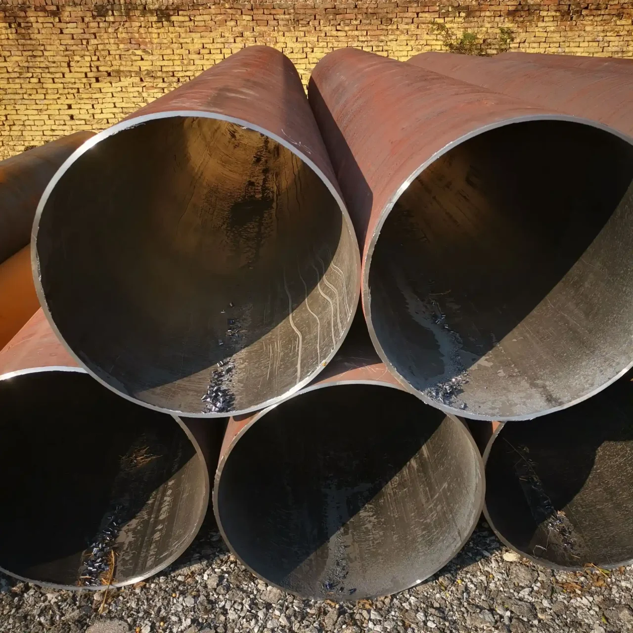
Core Principle and Technical Analysis of Medium and High Frequency Heat-Expanded Seamless Steel Pipe Process
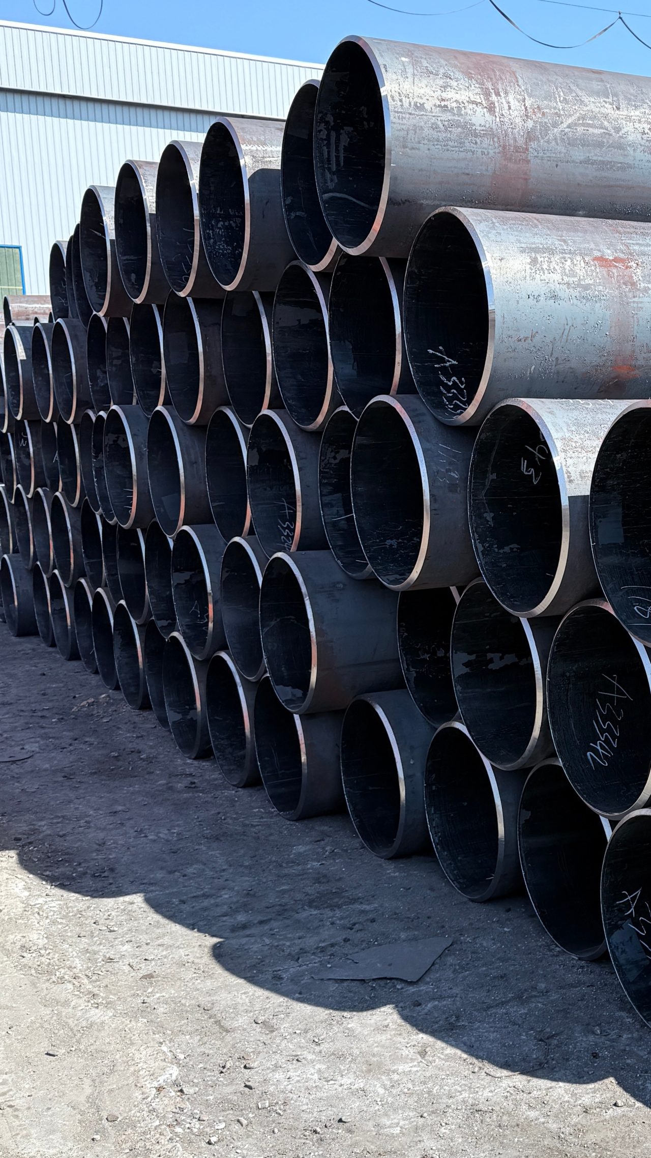
Development History and Current Situation of Medium and High Frequency Heat-Expanded Seamless Steel Pipe Process
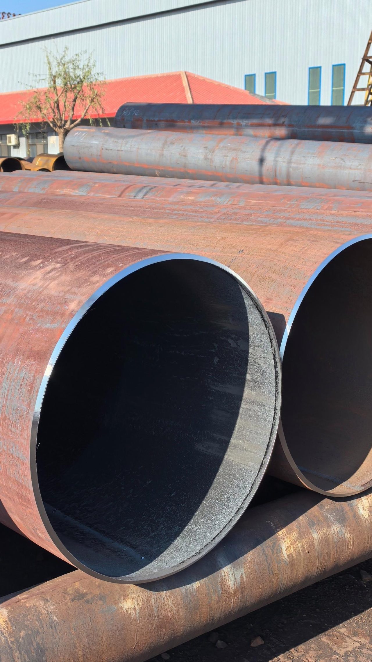
Technology, Application and Development Trend of Guanzhong Medium and High Frequency Heat-Expanded Seamless Steel Pipes
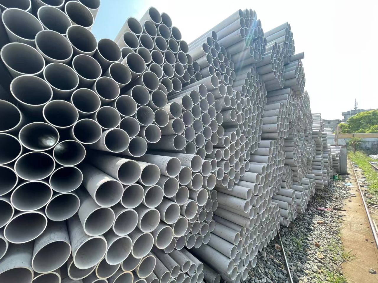
ASTM A276 TP304/304L Stainless Steel Welded Pipes: Standards, Properties, Manufacturing, Applications and Quality Control
The pursuit of integrity in maritime engineering often anchors itself to a single, critical component: the seamless steel pipe. To understand the trajectory of research and development in marine seamless pipes, one must look beyond the simple geometry of a hollow cylinder and see it as a metallurgical response to the unforgiving synergy of high pressure, thermal cycling, and chloride-induced corrosion.
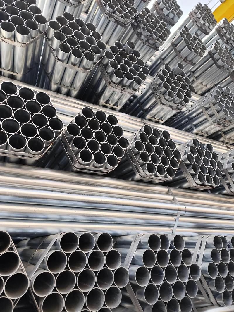
The ASTM A53 ERW Galvanized pipe is a masterpiece of balanced engineering—efficient to produce, high in performance, and incredibly durable. By adhering to the most rigorous interpretations of the ASTM standard and surpassing international benchmarks like JIS and EN, our company delivers a product that is built to endure.
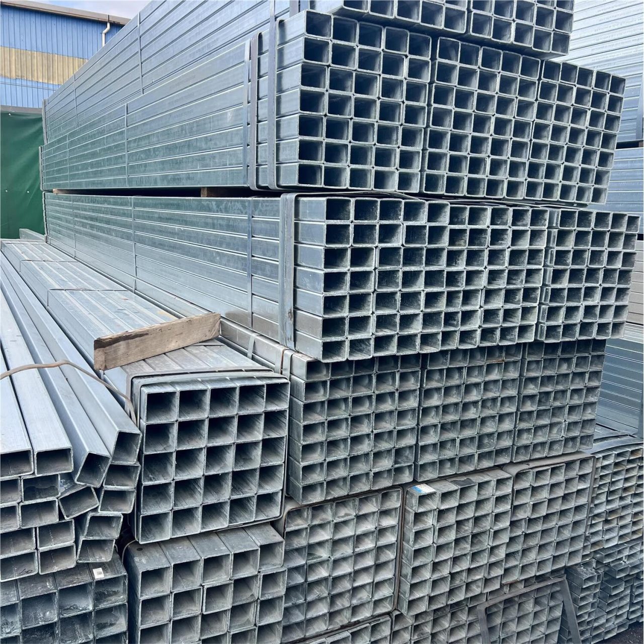
When you choose our galvanized Square Hollow Sections, you aren't just buying steel; you are investing in a structural foundation that is scientifically optimized for strength, chemically protected against the elements, and certified to the world’s most demanding standards.

However, 904L remains the indispensable choice for complex chemical environments where seawater is mixed with reducing acids, or for stagnant systems where its copper content may aid in resisting specific types of bio-corrosion. Furthermore, if the application requires extensive cold-forming or involves cryogenic conditions, the pure austenitic nature of 904L provides a level of reliability that the duplex structure cannot guarantee.
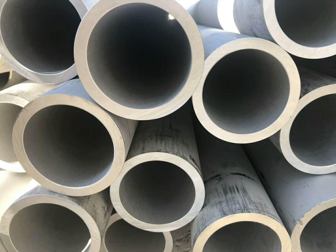
Ultimately, the 904L pipe is a testament to the power of precise alloying. It is a material that accepts the challenge of the most aggressive chemical environments, providing a service life that far exceeds standard stainless steels. By mastering the delicate balance of nickel, chromium, molybdenum, and copper, we provide a conduit that is as reliable as the physics upon which it is built.
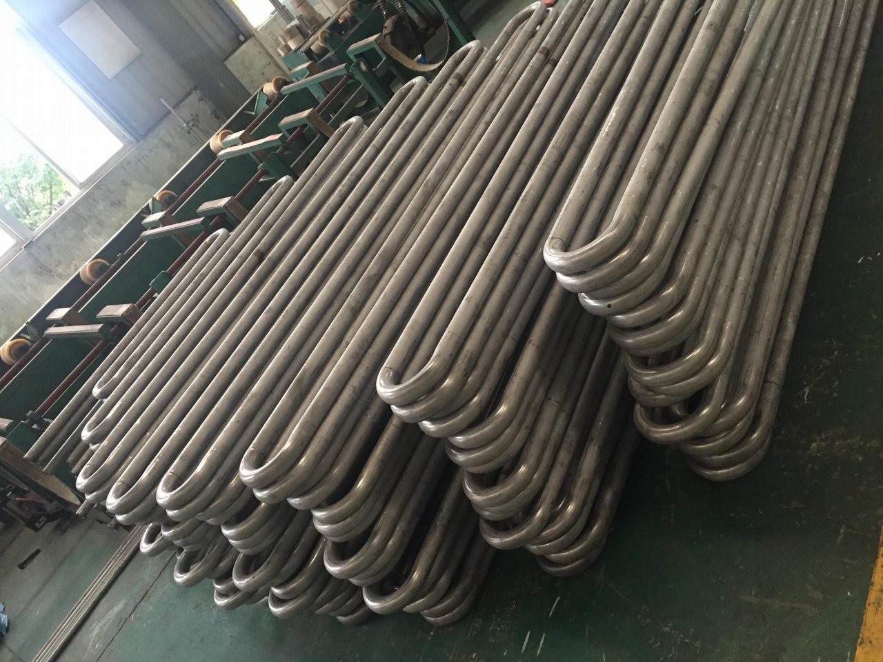
In advancing the technical narrative of our UNS N04400 ASTM B165 U-Bend tubes, we must pivot from the foundational metallurgy toward the sophisticated intersection of fluid dynamics and long-term structural reliability within the heat exchanger bundle.
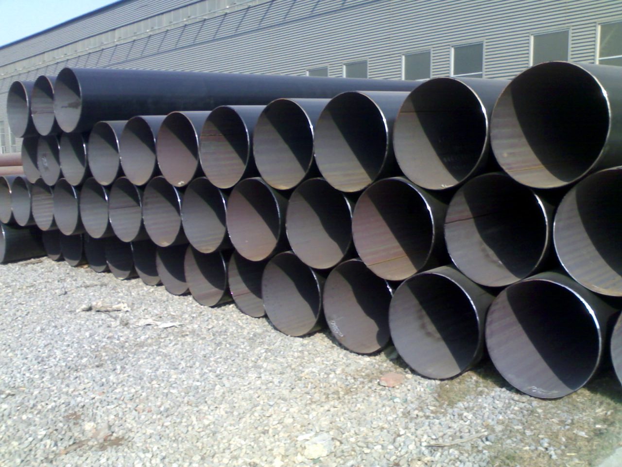
In summary, the technical success of EN 10219 pipe relies on a deeply integrated relationship between the chemistry (controlled by $\text{CEV}$ for weldability and $\text{P}/\text{S}$ for toughness), the manufacturing process (cold forming for efficiency and work-hardening), and the final mechanical guarantees (yield strength and low-temperature impact energy). The progression from S235 to S355J2H is an engineering-driven pathway, providing a graded spectrum of performance that allows designers to precisely select the most efficient and safe material for any given structural task. The inherent structural efficiency of the hollow section form, combined with the excellent weldability and guaranteed toughness of these $\text{EN}$ grades, ensures their continued preeminence as the material of choice for the world's most vital structural works.
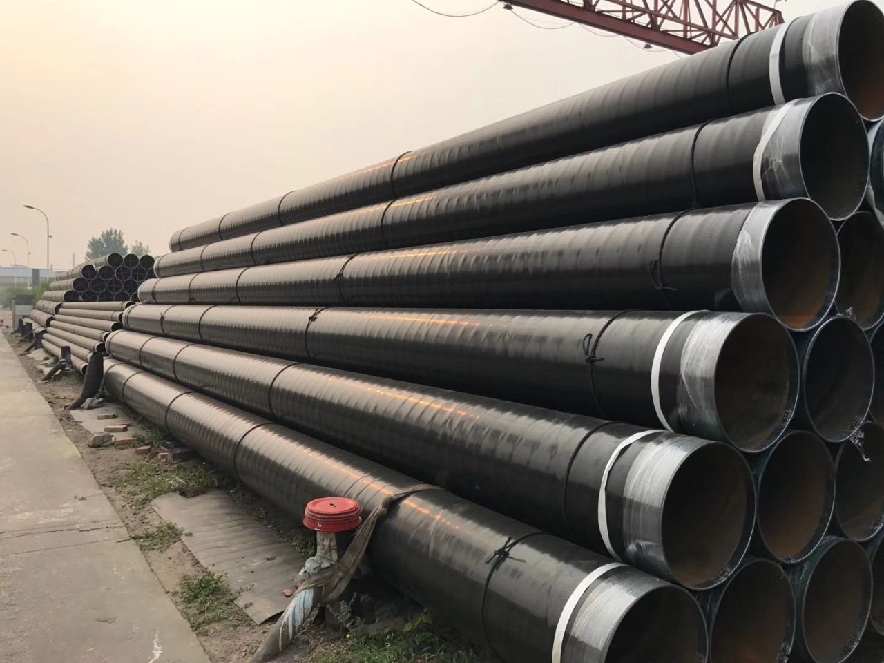
The API 5L Carbon Steel SSAW Pipe is a highly specialized piece of engineered infrastructure, a material solution fundamentally defined not by simple dimensional constraint or utility-grade corrosion protection, but by the relentless pursuit of high strength, reliable weld integrity, and exceptional fracture toughness, all necessary to ensure the safe, uninterrupted, and high-pressure conveyance of hydrocarbons, natural gas, or dense fluid slurries across vast geological and environmental landscapes. Unlike the familiar
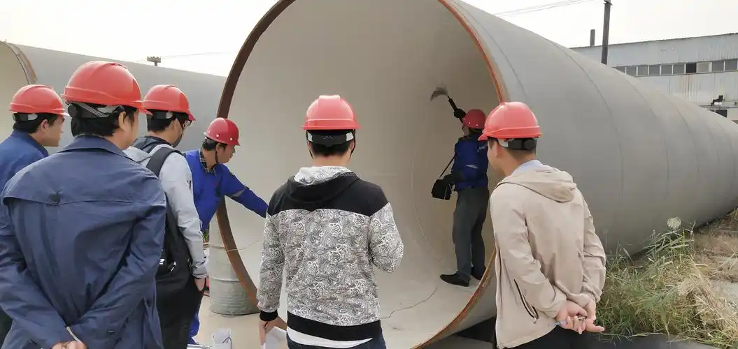
The investment in API 5L Grade B Large Diameter SAW Steel Pipe is not merely a procurement decision; it is a strategic commitment to decades of predictable, high-volume fluid conveyance, underwritten by the most stringent certification system in the global pipeline industry
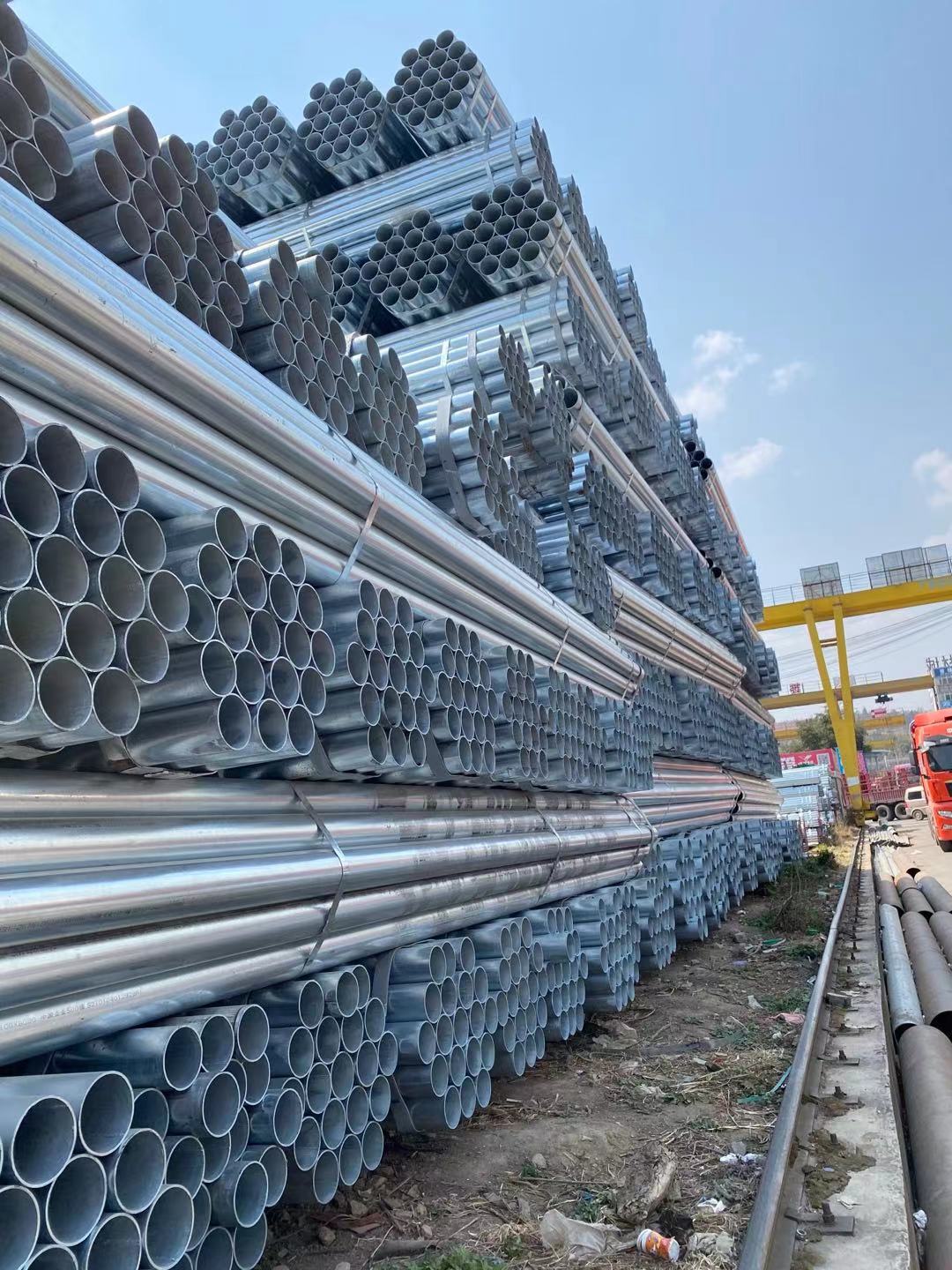
The Galvanized Steel Schedule 40 Pipe stands as an architectural pillar of conventional fluid transport, a design solution so ubiquitous in water pipeline infrastructure that its technical sophistication is often obscured by its sheer familiarity. Its continued dominance, even in the face of modern polymer and composite alternatives, is a testament to the optimized balance achieved between the raw, dependable strength of carbon steel and the elegant, self-sacrificial electrochemistry of the zinc coating
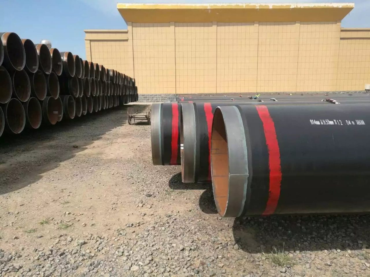
The pipe ends, which are left uncoated to facilitate field welding, require specific protection to maintain the cleanliness and integrity of the precisely machined bevels. The ends are protected with internal and external plastic or metal end caps to prevent physical damage, ingress of moisture, and internal contamination during storage and transit. For particularly long transit times, a temporary, easily removed corrosion inhibitor may be applied to the bare steel bevels to prevent surface rusting, ensuring the contractor receives a clean, ready-to-weld surface. This final logistical step closes the loop on Abtersteel’s commitment, ensuring that the high-integrity X60M PSL2 3PE LSAW pipe reaches the construction site in the same pristine, certified condition in which it left the factory.
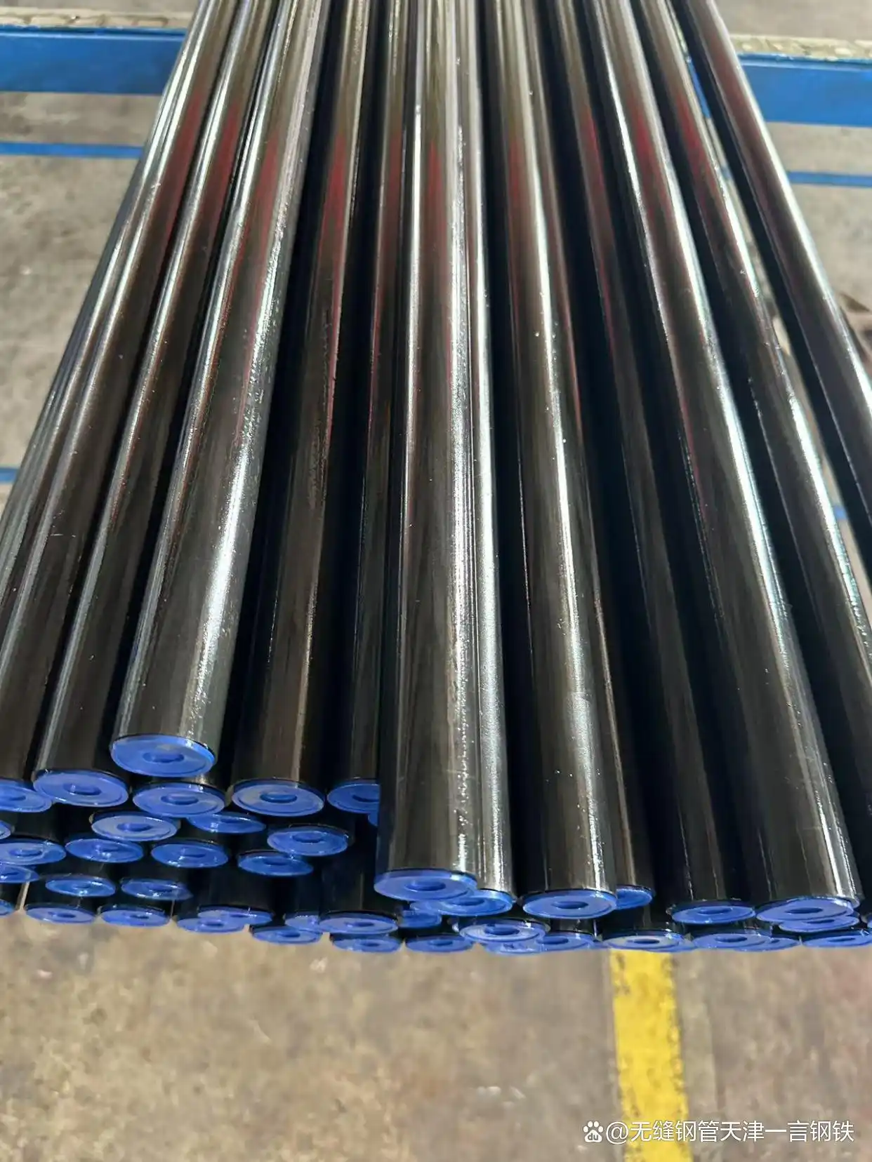
The DIN 2391 Grade St45 Seamless Pipe, supplied in the NBK condition, represents the pinnacle of precision steel tube engineering. Its excellence is a calculated outcome of advanced metallurgical control, severe cold-work plasticity, and meticulous thermal processing. Its functional superiority is validated by its proven ability to:
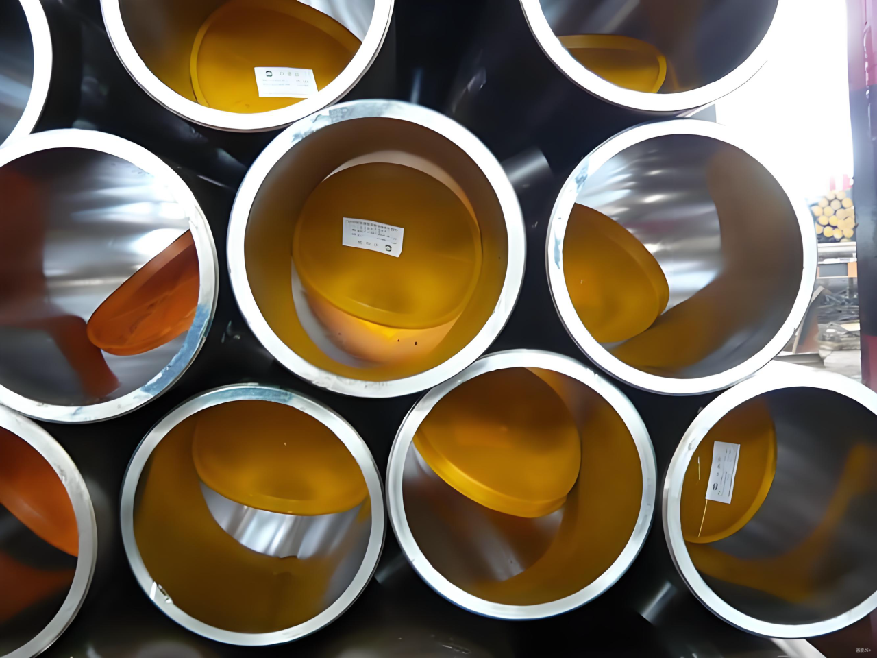
The DIN 2391 Grade St45 Seamless Pipe is, therefore, the product of choice where dimensional integrity is not a preference but a safety and performance prerequisite. Its use underpins the reliable operation of sensitive mechanical and fluid systems across every facet of modern industry, providing a foundational component that assures precision from the manufacturing stage all the way to decades of operational service.